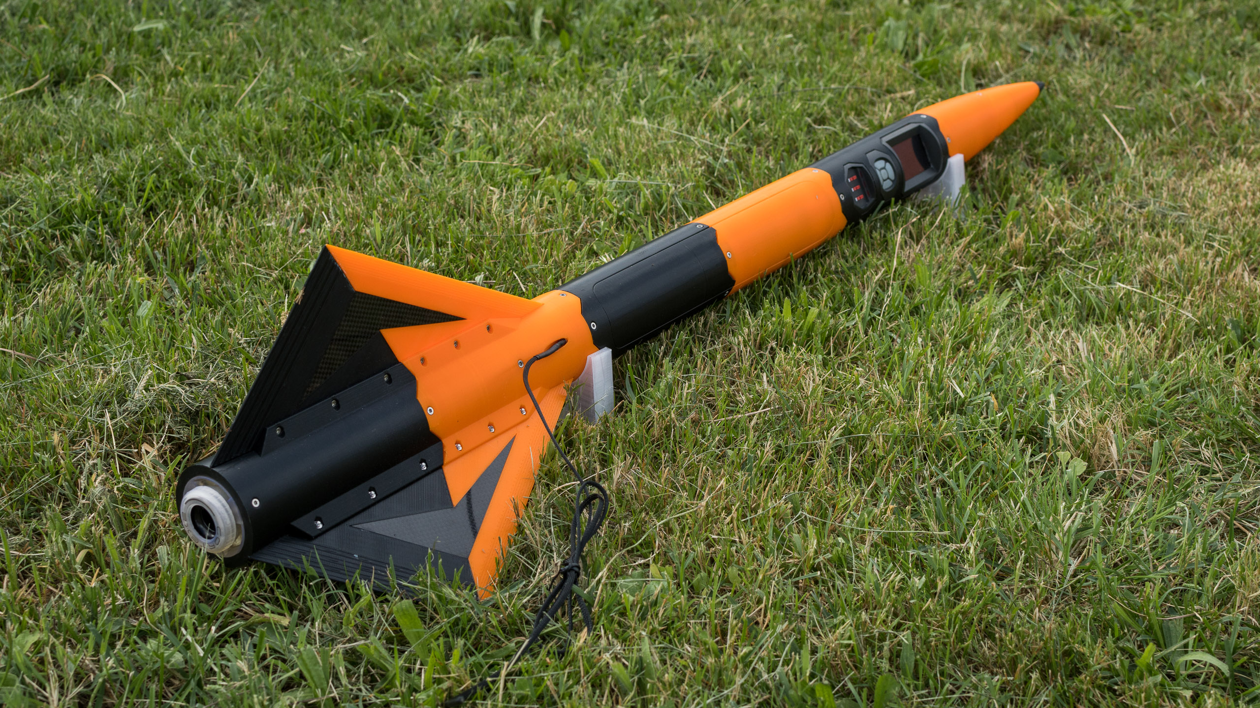
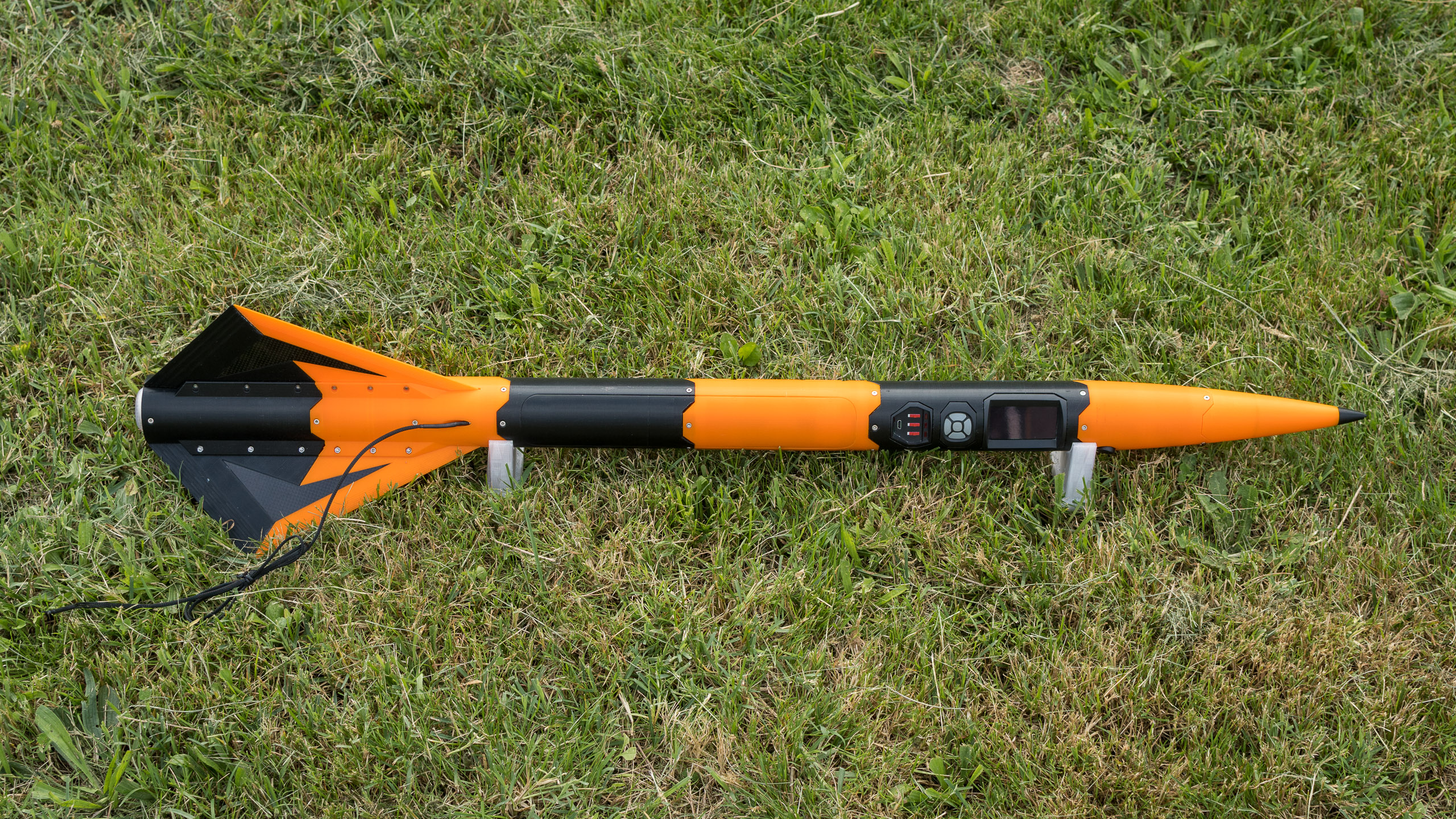
This is the long-overdue, direct follow-up to the first build log. The rocket is now finished and should be launched during the summer. Let’s go !
Motor stage
There has been a few improvements to the parts shown in the first article.
First of all, I was getting a bit concerned about the relative fragility of the High-Temp SLA resin used to build the motor’s compartment, it tends to be brittle, and I don’t want it to fail when the motor starts pushing. Since it is now confirmed that the motors we use won’t have the ejection charge, I don’t have to be concerned by hot ejection gases anymore, so I upgraded the top end of the motor casing : it is now made of a HT resin plate (for heat insulation) that rests against a solid push-plate 3D-printed in Polymax-PC (polycarbonate) with 100% infill. This way, the shear forces caused by the motor’s thrust on the screws and the fuselage are taken by the strong polycarbonate part, and the resin part only takes compression forces. Even if it shatters, the motor is still held in place from all sides.
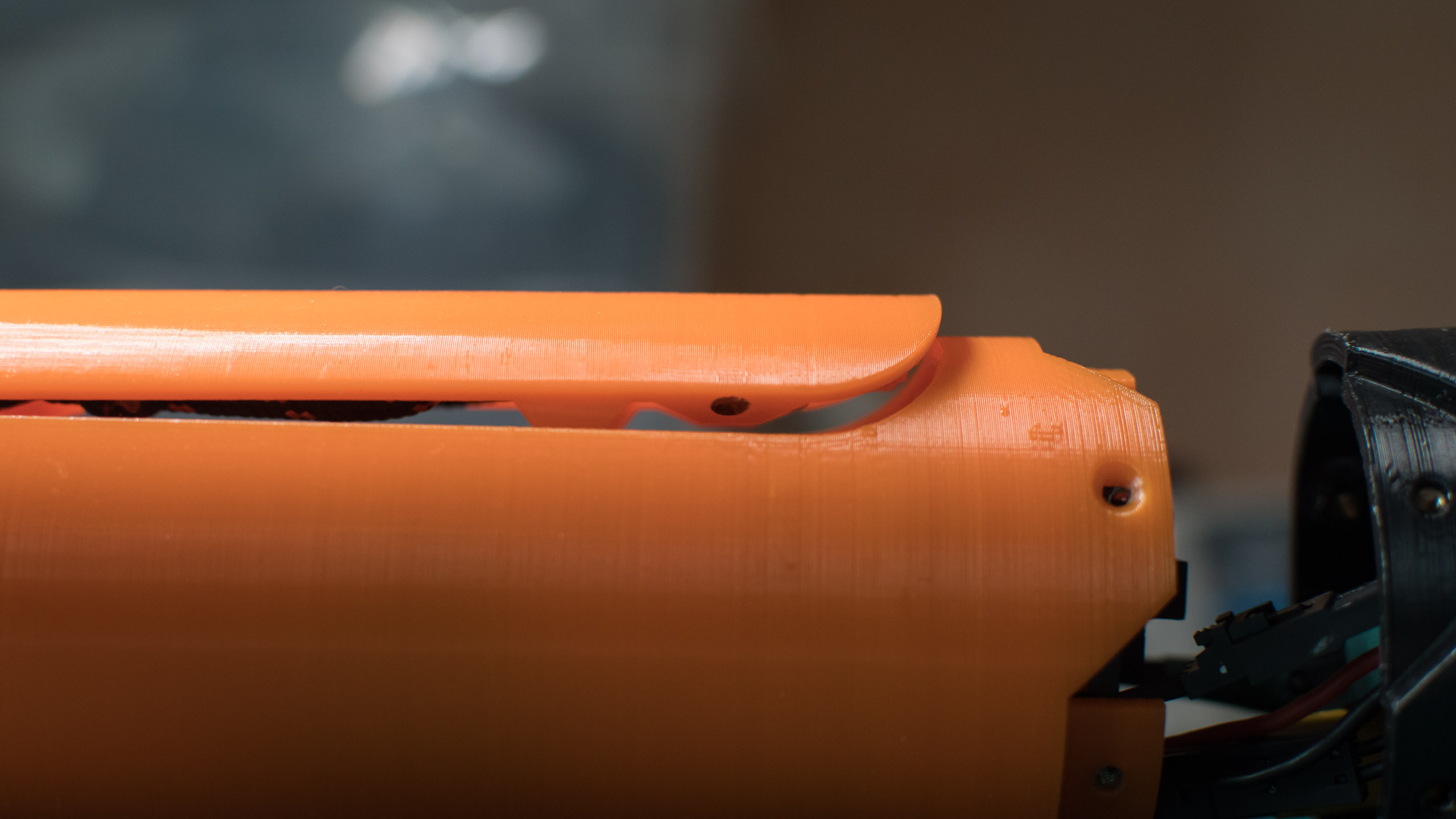
I also improved the design of the mechanism used for the retractable pads. It is now better optimized for printing which gives a better fit between the moving parts, it is sturdier, and easier to assemble. I also 3D-printed a custom shorter lever for the servomotor to use its full angle range and transmit more force to the slider.

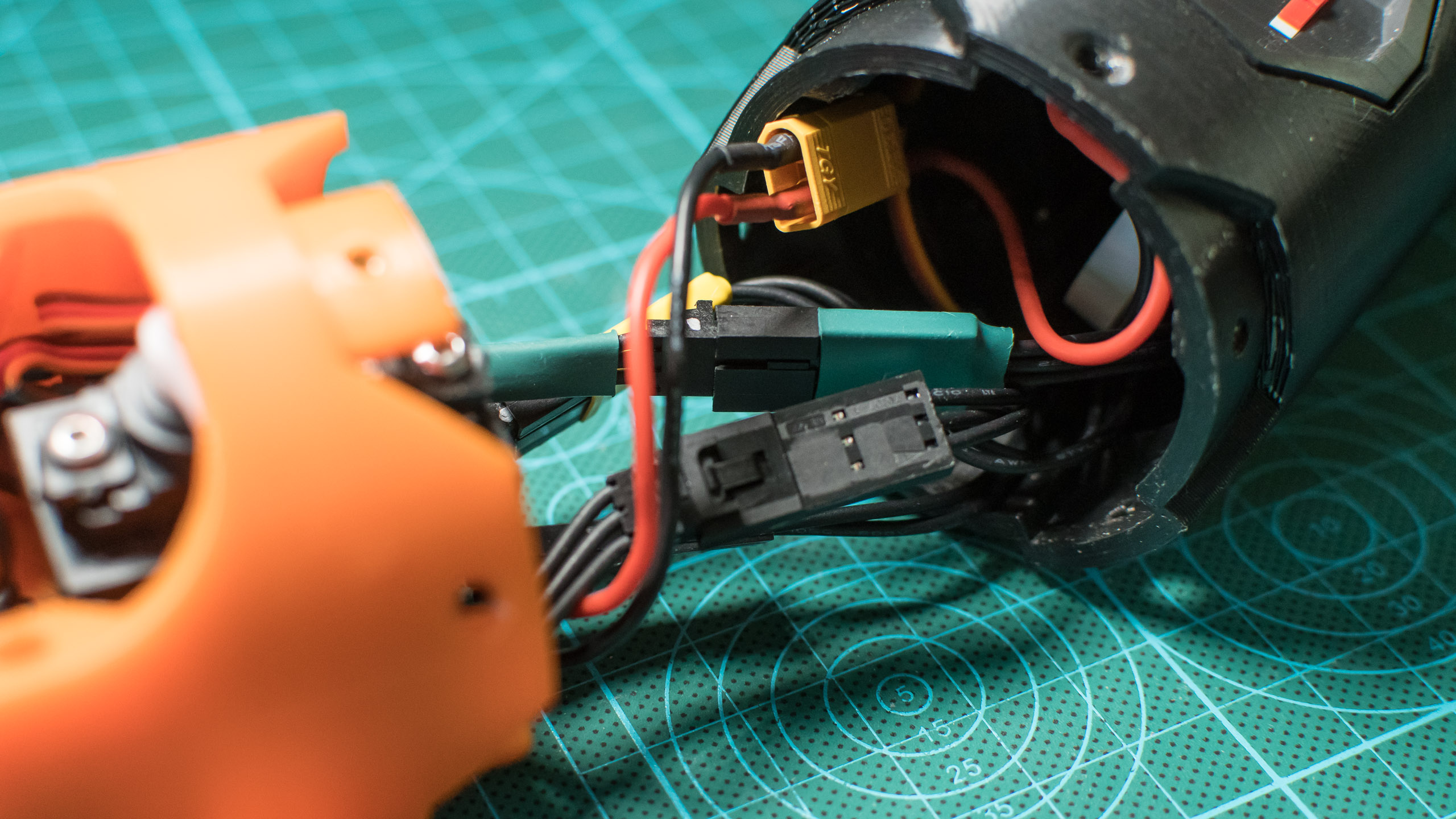
I’ve changed most connectors to use Molex’s SL series instead. These connectors have a locking tab that should make sure the rocket won’t fail because a connector unplugged itself during the acceleration of the launch.
Finally, I had fun with the ring that holds the motor in place : I added an embossed logo in the 3D model, then I poured black resin in the cavities and made it cure in the UV post-curing chamber. I then sanded the excess with fine-grain sandpaper to obtain a nice and smooth print of the rocket’s name.

Parachute compartment
The next part to be built was the parachute compartment. In order to avoid repeating the mistakes of the first rocket, it is now considerably larger and allows the parachute to fall with almost no resistance. While it may look like a simple compartment with a door, there are a few interesting things to note regarding its design :
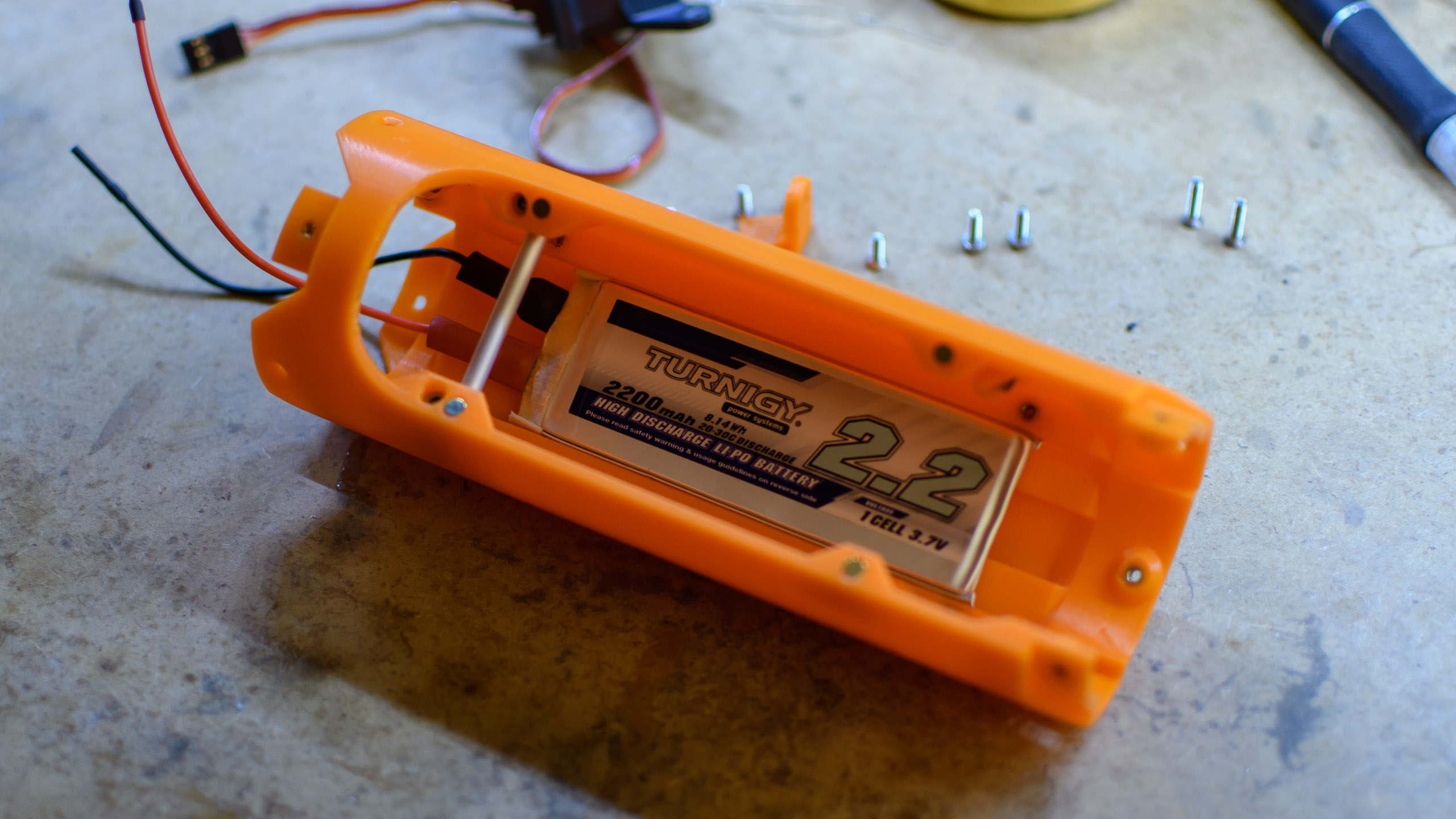
- The battery is hidden behind the back of the compartment, which helps place the center of mass at the optimal spot for stability :
- A separator is placed inside the compartment in order to separate the main line from the parachute itself and prevent them from being entangled during the acceleration :

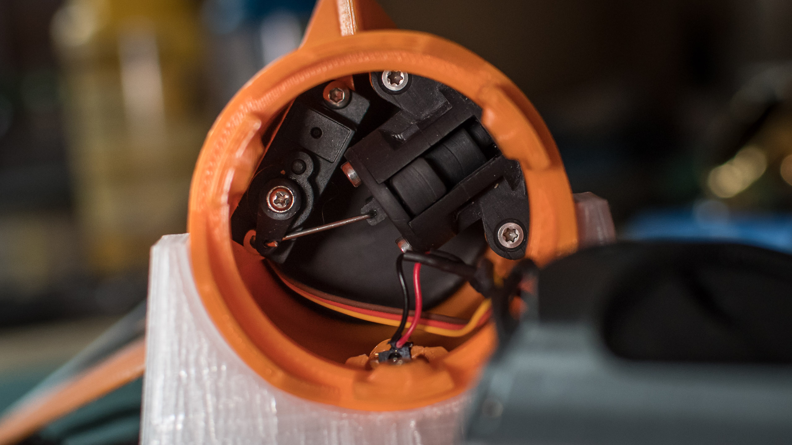
- 4 magnets are mounted on the sides, with 4 other corresponding magnets on the hatch (in a reverse-polarity configuration), to make sure that when the servomotor unlocks the door, the hatch has an initial repulsive force to eject it; the wind rushing into the slit should blow it away completely :
- Another magnet on the hatch activates a Hall-effect sensor in the rocket (the black box below the servomotor), allowing to detect when the hatch has been ejected :
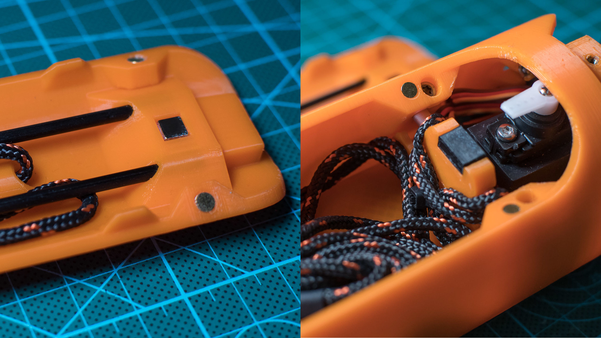
- The parachute line is attached on two points to an aluminum bar, which is itself solidly embedded behind a thick wall in the 3D-printed part, to make sure it won’t be ripped off when the parachute opens. This anchor point is placed above the center of mass to make sure the rocket will come back down with the nosecone up and the motor end will touch the ground first. I want to protect the Pitot tube and the nosecone, and I hope the fall speed (estimated at about 7.5m/s) will be low enough and the terrain soft enough to not break an aileron.

- Obvously, the hatch is attached to the main line to extract it with the parachute when it is ejected. It is important to mind where it is attached exactly : the hatch should not be able to touch the smaller lines of the parachute when it spins above during the descent, to make sure it won’t get tangled in them.

- The SWD connector used to program the main microcontroller is hidden beside the servomotor, to be accessible by simply opening the hatch without taking the rocket apart.
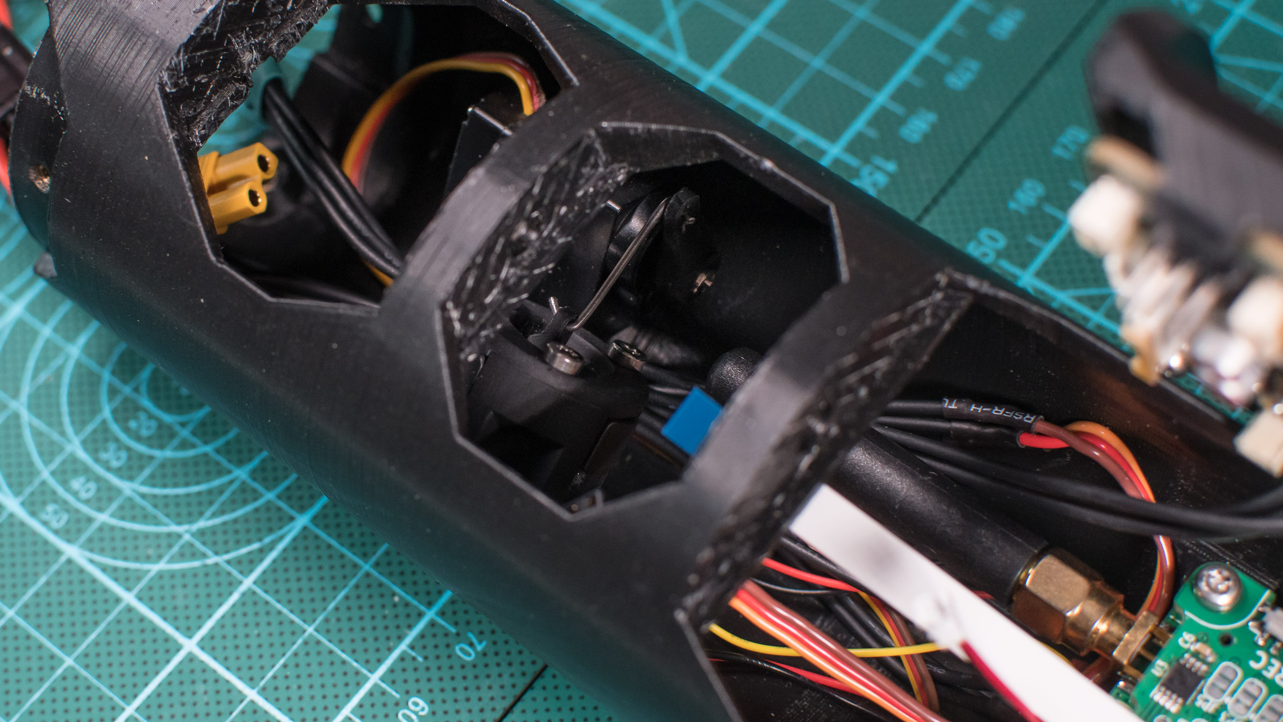
Electronics
This is a big chunk. There is a lot going on in this stage, and making everything fit was probably the most challenging aspect. Cable management was important here because there are moving parts (the upper retractable pad) that shouldn’t get blocked by or tangled with the large amount of cables going everywhere.
The electronics consists of 4 main boards : the flight controller, the “power” board, the “buttons” board, and the telemetry module. The flight controller is connected to the other 3 subsystems through FFC cables. The telemetry module is actually a standalone project on its own (it can and will be used in other projects) and will therefore be discussed in more depth in a following article.
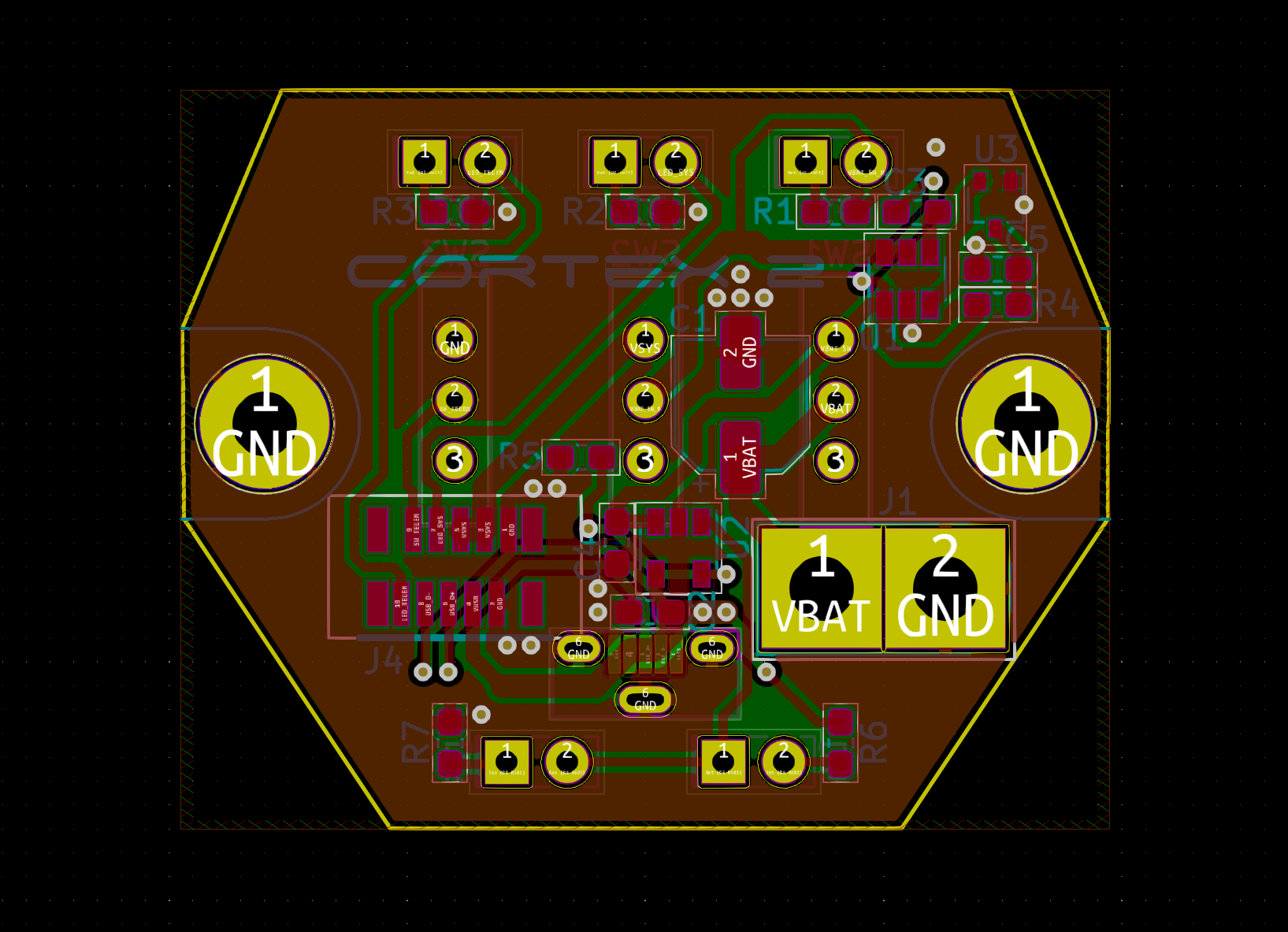
Power board
Let’s start with the “power” board. It’s a relatively simple PCB which connects to the battery and exposes to the facade 3 switches and their associated LEDs, as well as the USB connector. It also integrates a battery charger (powered from the USB so the rocket’s battery can be recharged directly from a phone charger) and a 3.0V under-voltage protection that turns the electronics off when the battery is empty.
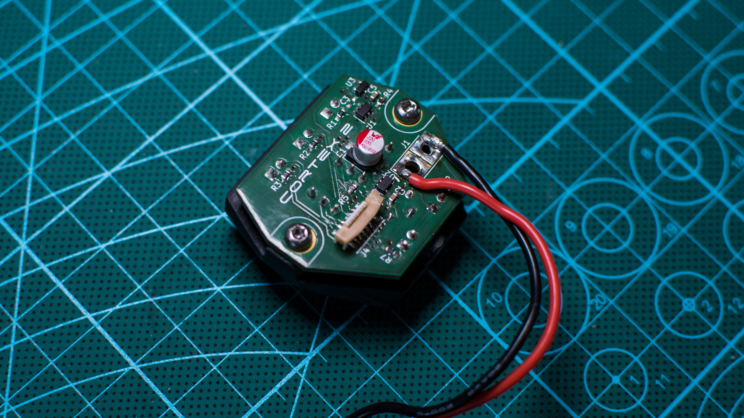
The front panel is 3D-printed with black resin and slides in place into the main fuselage part. The buttons, LEDs and USB connector are adjusted and soldered in place.
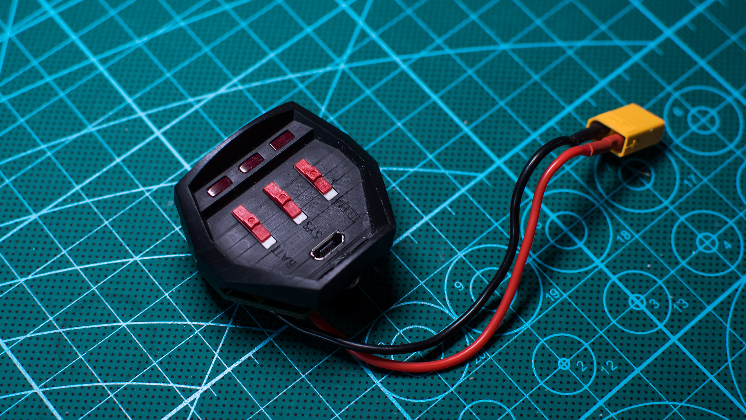
The 3 switches turn on respectively the battery, the power output, and the telemetry. The charger is connected between the first two switches : this allows to completely disconnect the battery when the rocket is stored (without even the small quiescent current consumed by the output pin of the charger) as well as allowing to charge the battery while keeping the rest of the electronics off. As for the telemetry switch, it is mandatory to make sure the projects do not interfere with one another.
Power output, LED signals, and USB data lines are routed to the main board through the flat ribbon cable.
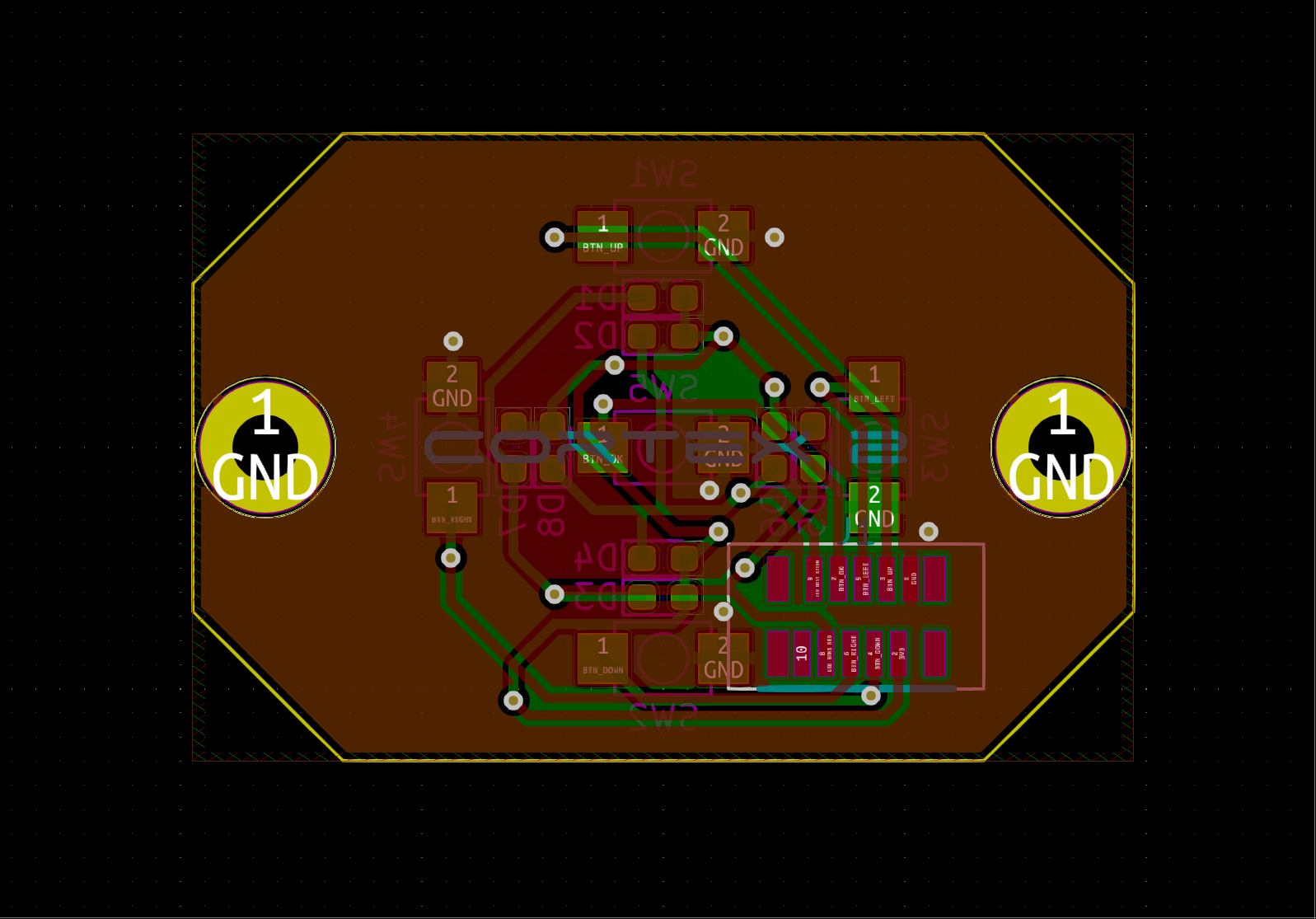
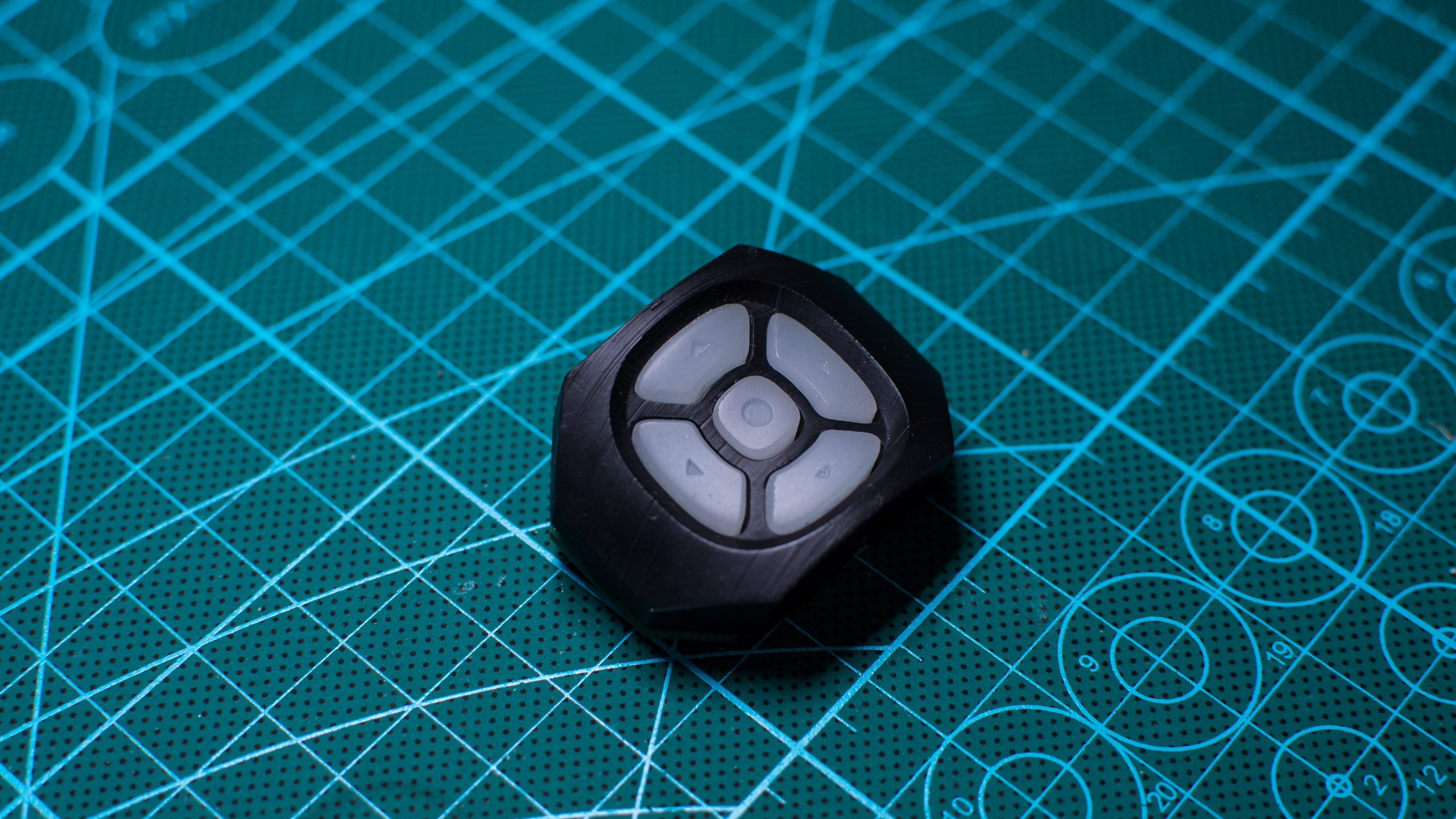
Buttons board
This is an even simpler PCB. It features 5 buttons, 4 green LEDs, and 4 red LEDs. The front of the buttons is made of Simpact 60A polyurethane resin from Smooth-On, cast into a silicone mold. The mold itself was cast from an SLA 3D-printed master. Since the Simpact is slightly translucent, the color of the LEDs is visible, which allows the buttons to visually react to the user input and flash according to the current state of the rocket.
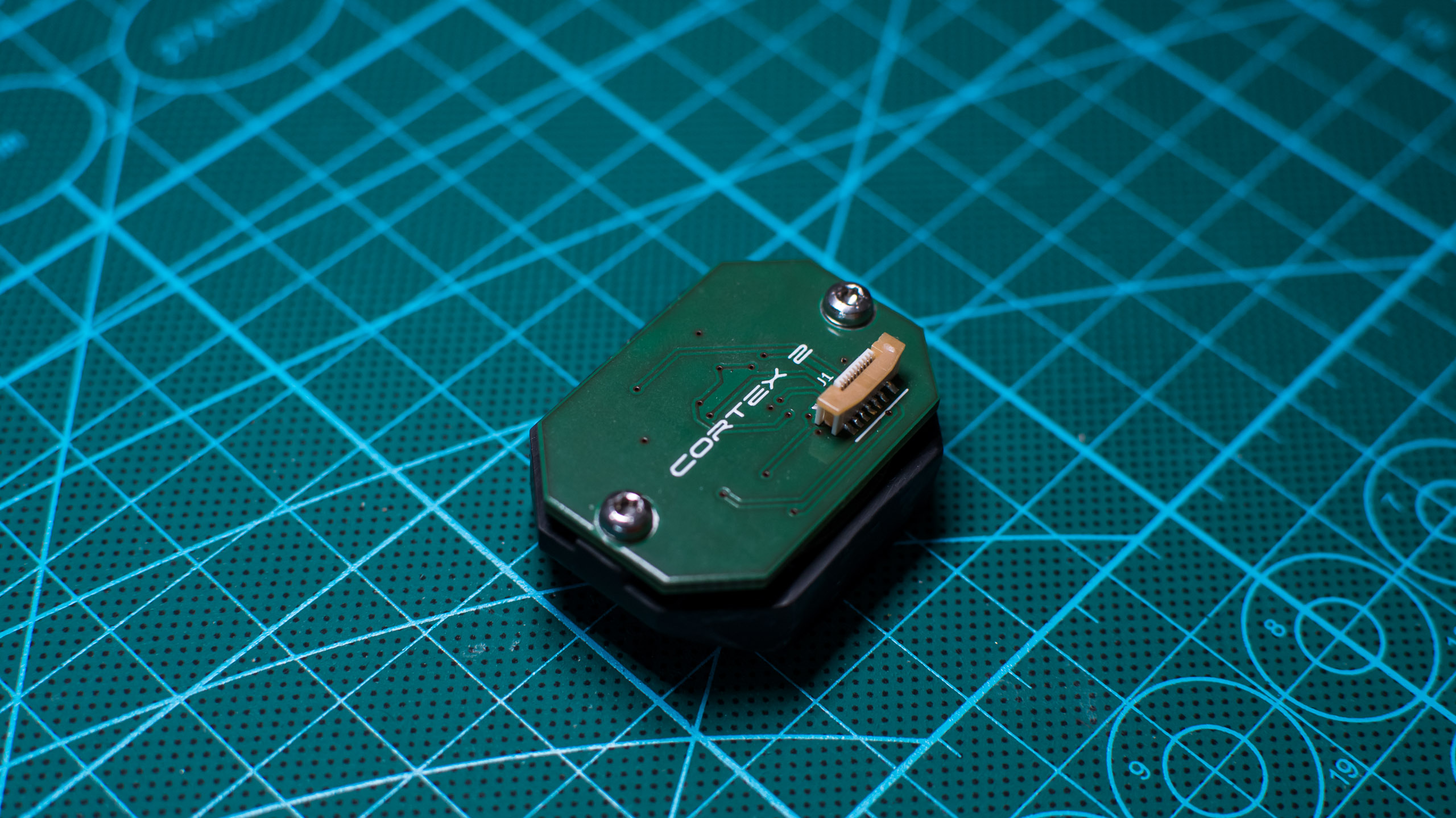
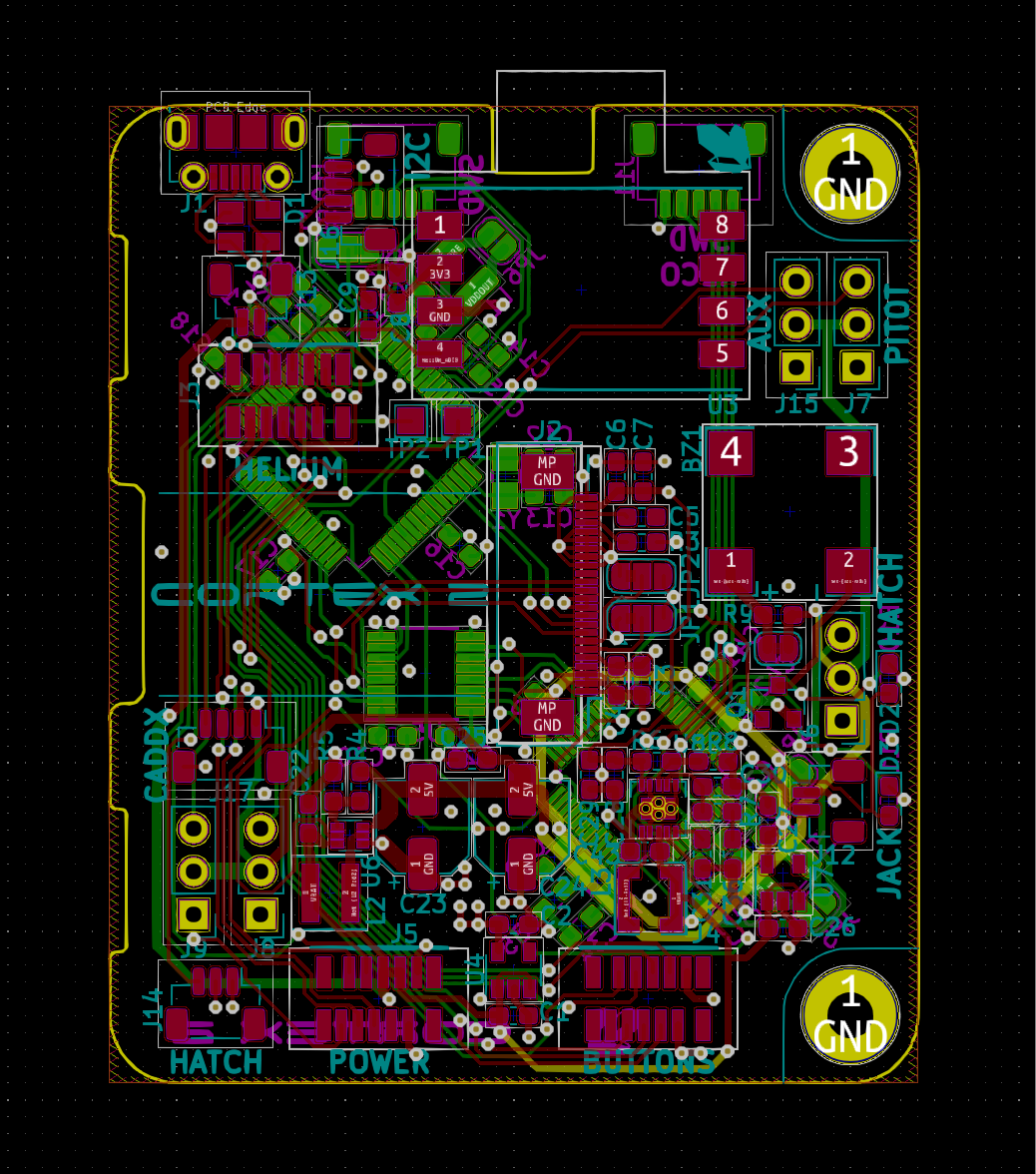
Flight controller
This PCB is a bit more complicated. It contains, among other things :
- a large OLED screen
- the main microcontroller that drives the screen and most of the peripherals
- a second microcontroller dedicated to the recovery system, i.e. the jack and the servomotor of the hatch
- a 5V step-up regulator to power the servomotors
- a very noisy buzzer
- a differential pressure sensor for the Pitot tube
- a lot of connectors

All the microcontrollers are ATSAM4LS chips from Microchip. Those are the same Cortex M4 microcontrollers that I use in all my projects with the help of the libtungsten HAL library. Thanks to the dedicated microcontroller, the recovery system is completely autonomous. This way, even if the main microcontroller crashes for any reason during the flight, the parachute should deploy without any issue and I should be able to get the rocket back in one piece. The two MCUs can communicate through SPI, which allows the main system to change the current ejection delay (so it is configurable from the GUI) and to get the current stage of the hatch and the jack.
As an added protection, the recovery microcontroller has a watchdog enabled in the firmware that resets the chip and open the hatch in case of a software crash.
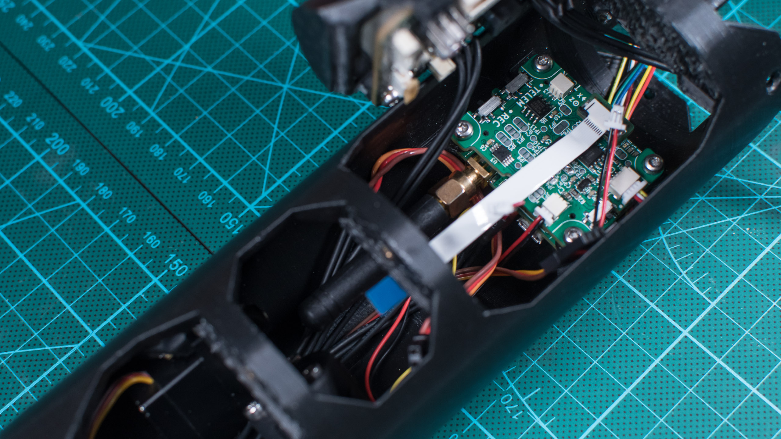
Telemetry module
As stated before, the telemetry module, called Helium, is a standalone module that contains another Cortex M4 microcontroller, a LoRa 869MHz transmitter, a Flash storage chip, an extension port, and a few sensors : mainly a temperature sensor, a pressure sensor (i.e. an altimeter), and a 6-axis IMU. It communicates with the flight controller through an adapter plugged into its extension port, mainly over I2C. This is a bidirectional communication : it allows the main MCU to get the current values from the sensors (to display them on the screen), and the Helium module to get the current state of the rocket’s flight controller (jack, parachute deployment, …) to record and transmit them.
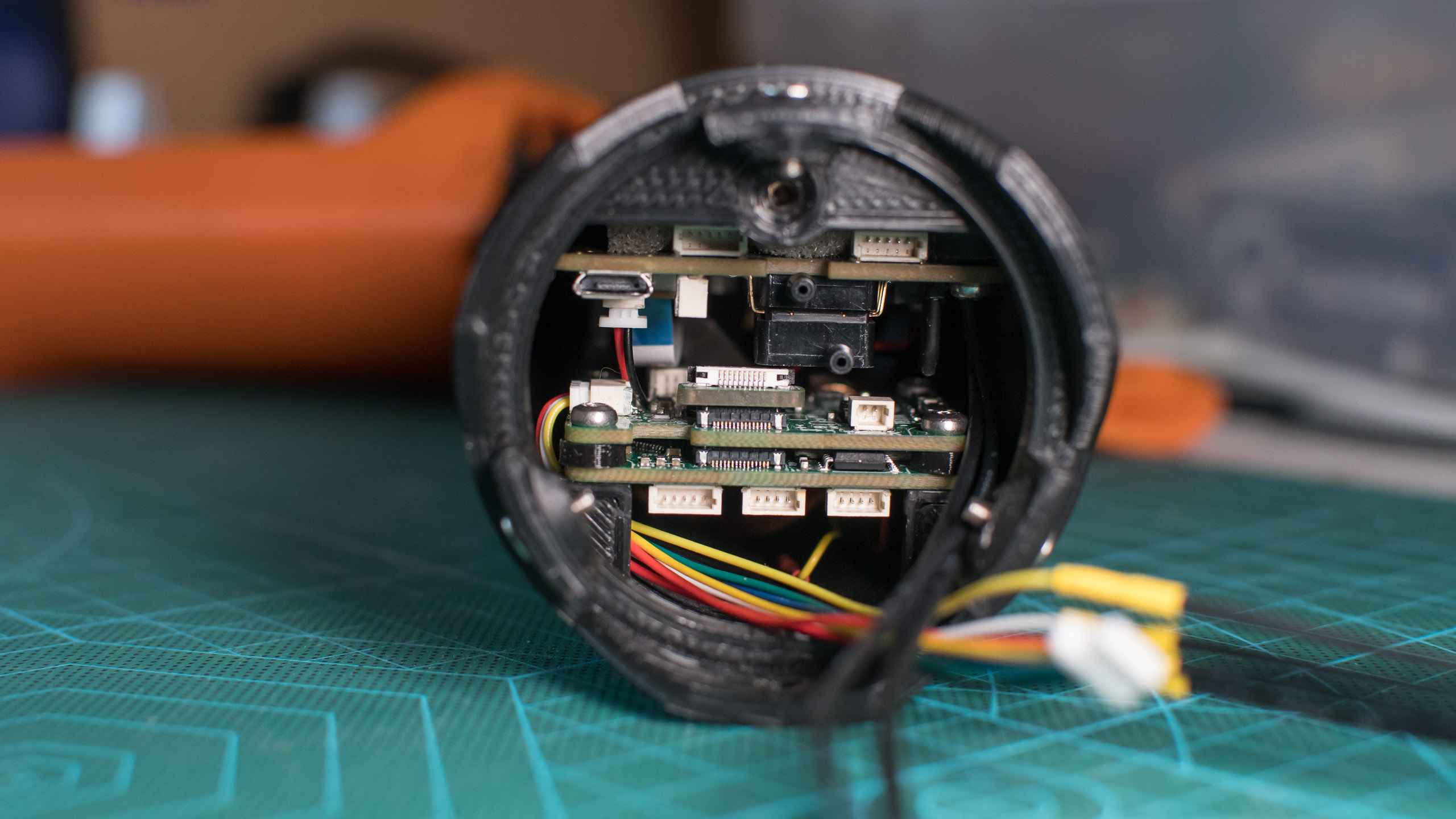
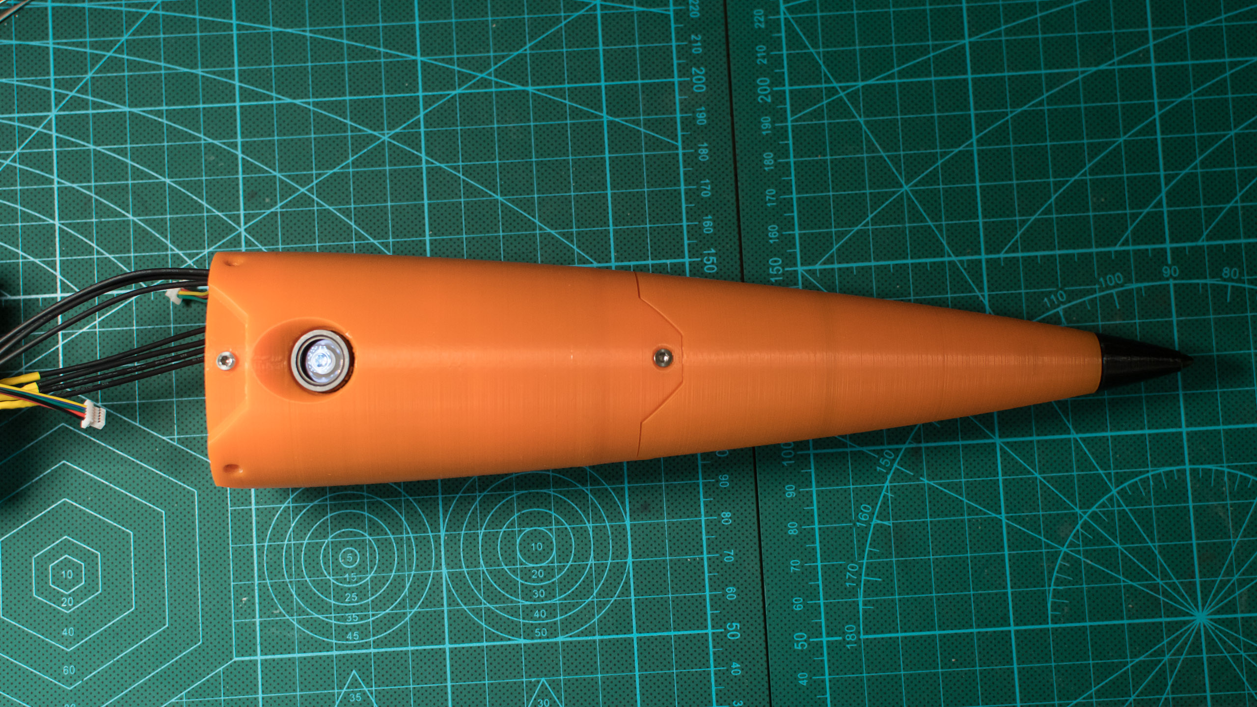
Nosecone
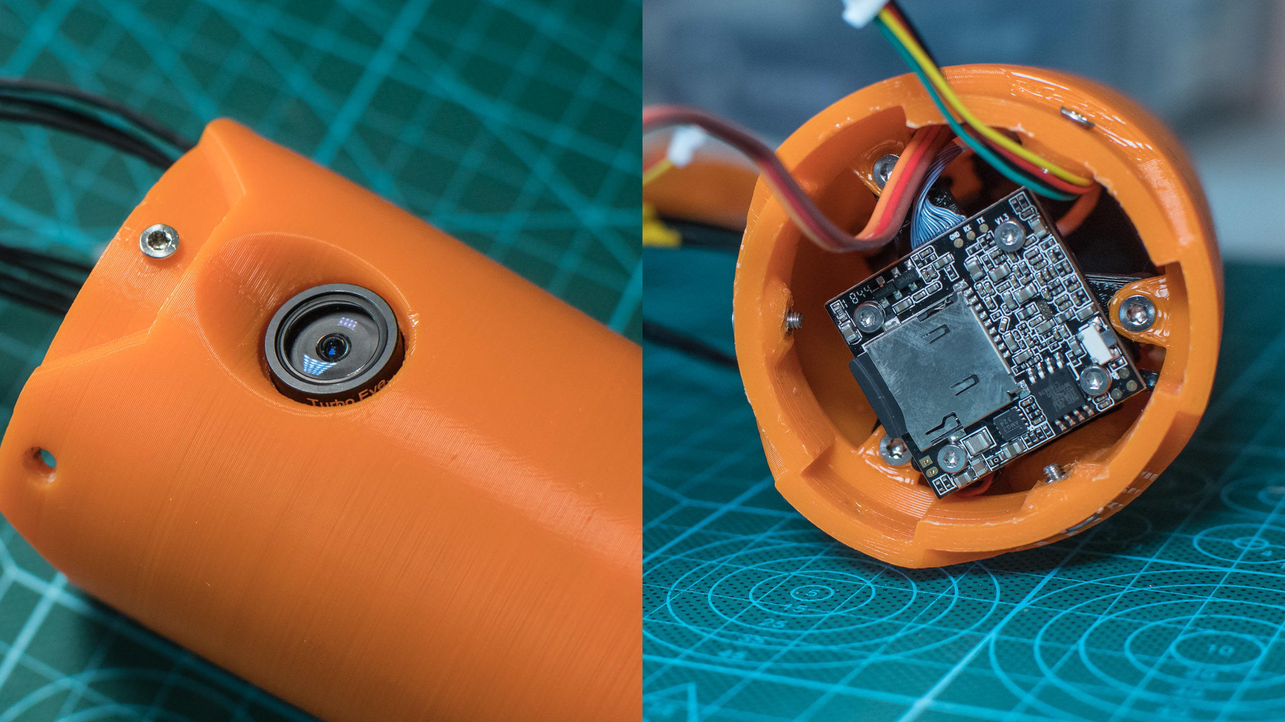
The nosecone houses three subsystems : the camera, the GPS receiver and the Pitot tube.
The camera is a Caddx Turtle originally made for FPV. Because it is designed to be integrated into a drone, it doesn’t have a case but only a PCB and the actual camera module connected through a small cable. This makes it easier to integrate in the pretty tight space available in the nosecone. Unfortunately I managed to brick this camera while trying to update its firmware, so for now it doesn’t work, but I hope I will be able to repair it before the launch.
Above the camera is the GPS receiver, that needs to have as little obstruction from the sky as possible. It is based on a uBlox Neo M8N chipset, and was also originally made for drones.

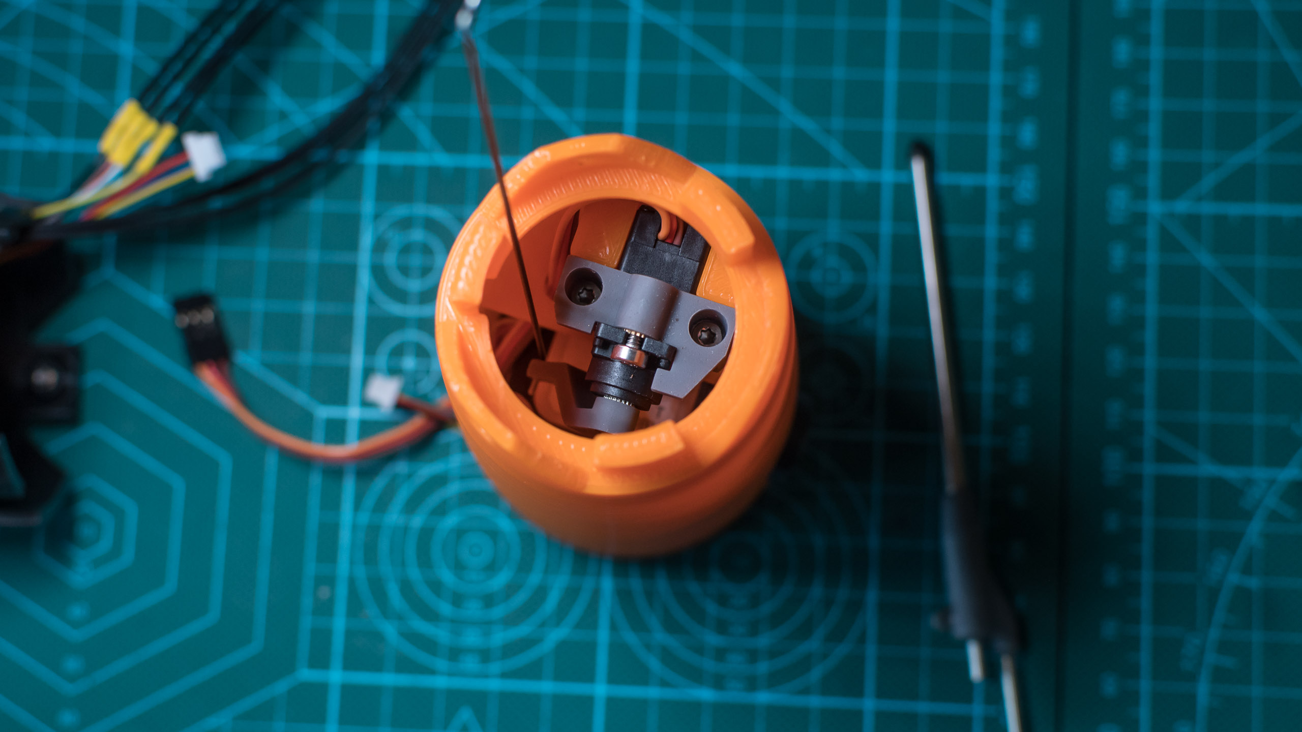
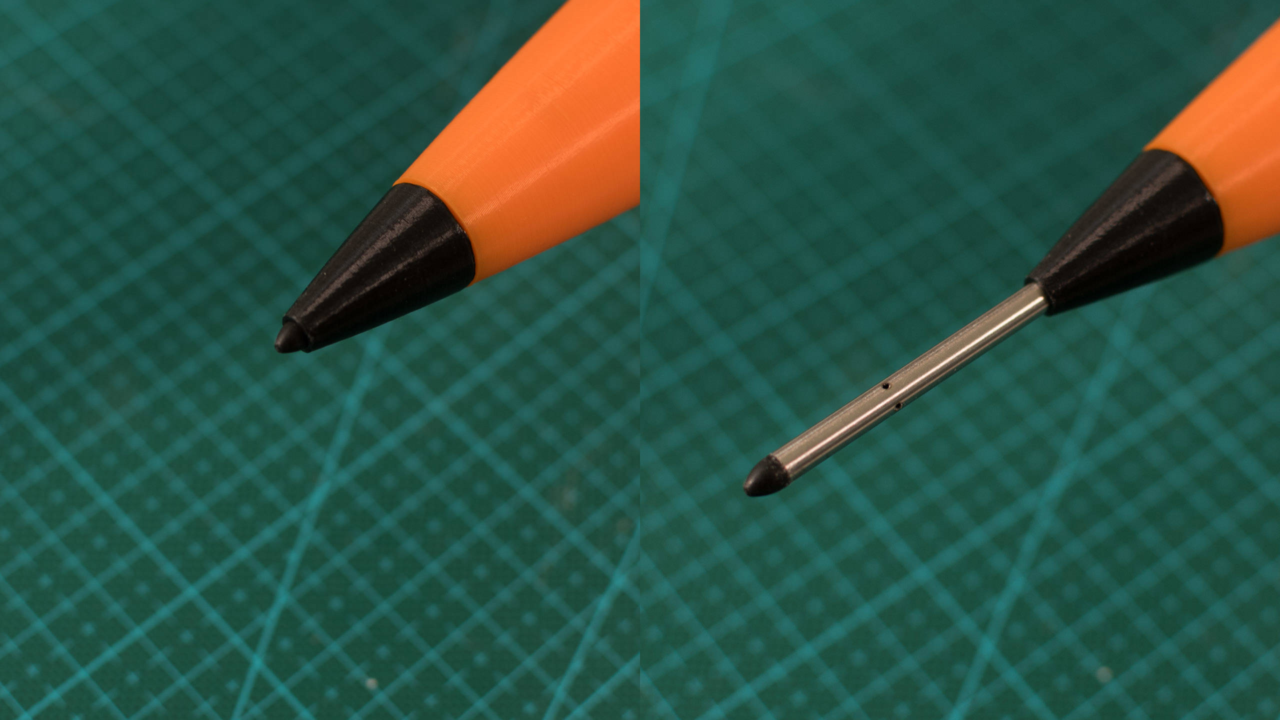
Finally, the Pitot tube. Because it is a fragile part that sticks at the top of the rocket, I made it retractable (just like the pads for the ramp) with a servomotor, to pull it inside the nosecone when it is not needed. The flight controller retracts it automatically just before deploying the parachute to make sure it won’t be snapped by one of the lines.
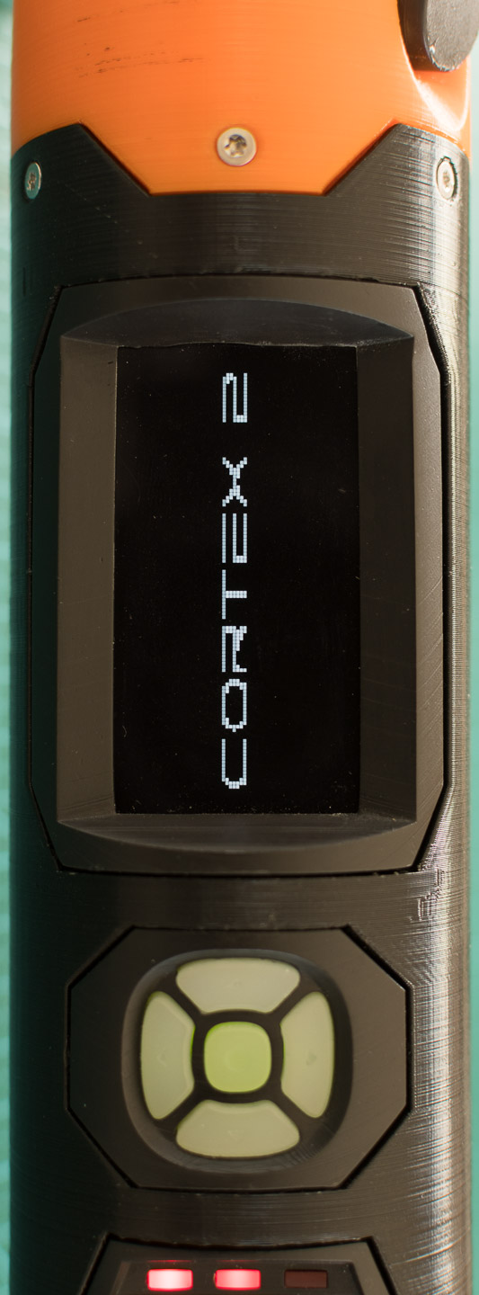
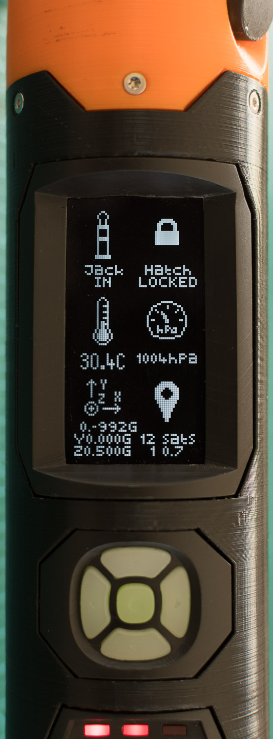
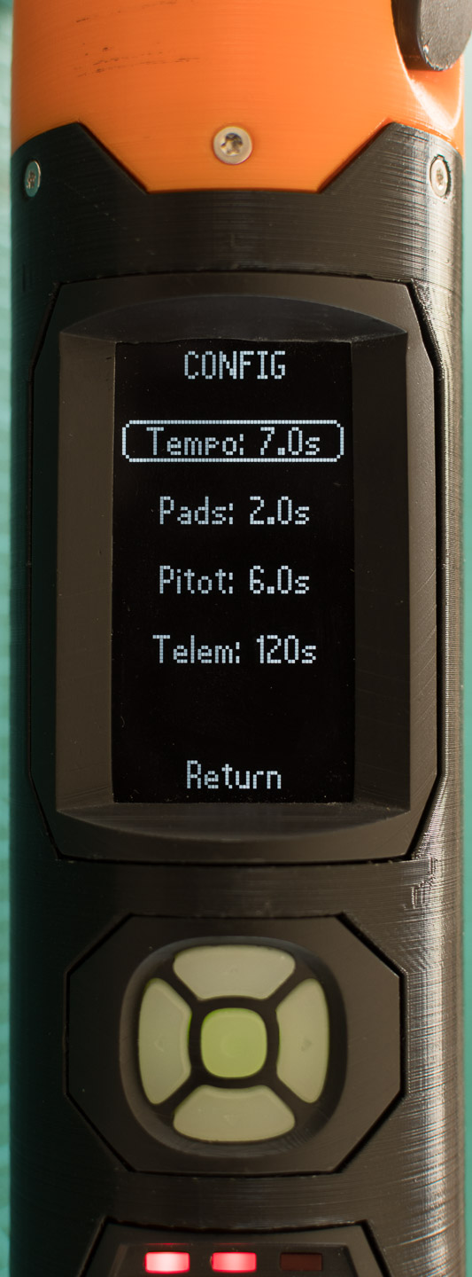
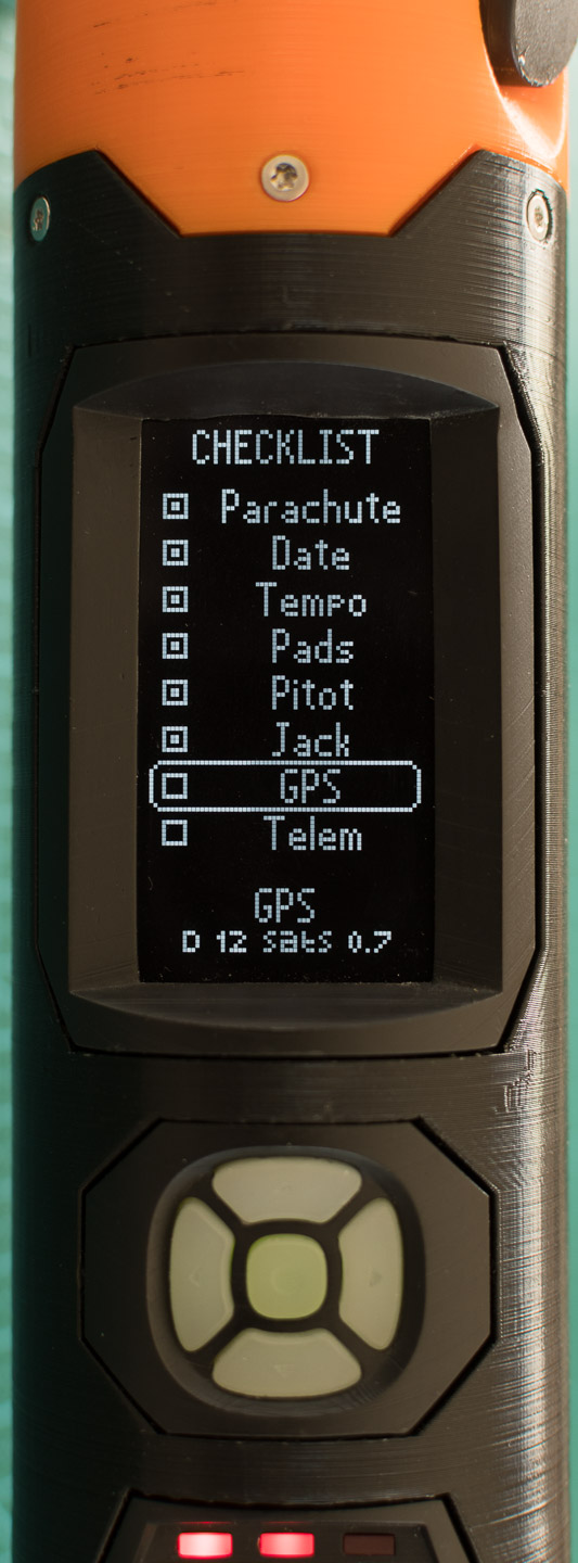
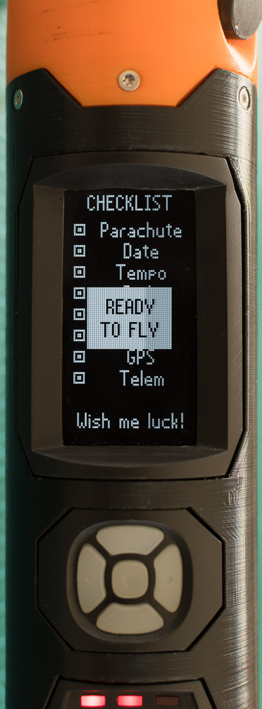
GUI
The OLED screen and buttons are used to display a small user interface that shows the measurements from the sensor (for example, to make sure the GPS has acquired a lock), to control the actuators, and to configure the timings of the flight controller. It includes the pre-flight checklist to make sure all the systems are ready and configured correctly for the launch.


Wrapping up
That’s it, the only thing left is to wait for the launch ! I’ll post the results here.

Please add me to your list for launch updates/photos/videos when those will be available. Inspiring work!
Hi,
Thanks for your interest, I’ll post the results with photos and videos of the flight as soon as possible !
Nice rocket. I look forward to its first flight.
Were you able to test fly it yet? Do you have the stl files to recreate this model?
I did last summer, thanks for reminding me that I need to publish an article with the results.
I don’t mind publishing the STL files but there are a lot of them with different materials, print settings (some are FDM and some are SLA), and external parts required, so I guess it would require a full build tutorial which would take a long time to write. Are you interested in building this rocket yourself?
Yes I am
Very impressive build, I hope the flight went well. Would love to build one if you would ever consider sharing your files. Great stuff!
I am interested in building cortex 2, can you please send the stl files?
Hey, I love the build! Any updates on whether files will be public soon? I would love to implement some design features into a rocket of my own.
Hello! I learned that your rocket was produced with many 3D printer materials and has many parts. I plan to produce all of them with ABS. To produce this, I need all of your .stl files. Can you share them? Even if you don’t have .stl files, it would be better if you could share them as .sldprt or .step files.