
Wait, Cortex 2? Where is the first one?
Cortex was a minirocket project launched during the 2018 edition of the C’Space, a French event allowing students to build and launch experimental rockets. It featured an entirely 3D-printed structure, embedded recording of physical parameters, a Bluetooth configuration interface (via an Android app), a GPS and a retractable Pitot probe, all of this built around three Cortex-M4 microcontrollers which obviously gave it its name. It was designed, among other things, as an experimental platform for libtungsten.
While it successfully qualified to fly, the rocket met the ground (and therefore its tragic end) at a velocity somewhat above the expected value, when its parachute failed to deploy.
Gravity is not always your friend.

The recovery of the hatch (the rocket itself was never found and is still buried somewhere in the swamp) allowed to find the culprit : the small 3D-printed part which linked the parachute to the hatch, and was supposed to pull the parachute out of its compartment, detached from the hatch. This is when I remembered that when I printed and glued this part into place (which is the very last thing I did on the rocket, a few hours before leaving for the event), I forgot to clean up the Dimafix residues from the buildplate on the part. Of course the CA didn’t hold. Dimafix is exactly supposed to avoid the part from sticking once it has cooled down. 3 years of design and building crashed because of a newbie mistake. Meh.
Ho, well. A draft of Cortex 2’s plans were complete before the end of the C’Space.

Fuselage construction
The old Cariacou motor used for the last decade finally retired this year, to be replaced by a Pro24-6g motor from Cesaroni. While both have similar total impulses (meaning they give about the same amount of velocity to the rocket in the end – for the mathematically inclined, this is the integral of the thrust curve), they have very different shapes : the Cariacou was short and large, while the Pro24 is almost twice as long and a lot thinner. This, naturally, lead to a matching geometry of the rocket : thinner (from 72mm down to 60mm) and longer (from 80cm up to slightly above 1m).
The global construction is similar : 3D-printed segments bolted to one another, whose height are limited by the Z axis capability of my Ultimaker2 (20cm). Cortex was sturdy but heavy, and PLA is stronger than I thought, so junctions will be smaller (1 set of 6 screws, instead of 2 sets of 4 screws). Since the rocket is longer, the numbers of segments jumps from 5 (ailerons-batteries-parachute-electronics-nosecone) to 7 (ailerons*2-parachute*2-electronics-nosecone*2).
Ailerons
The change in shape lead to other changes. A longer rocket means a higher static margin (basically, the distance between the center of mass and the center of aerodynamic pressure of the ailerons), which, if I kept the same ailerons as the first Cortex, meant an overstable rocket.
A rocket is overstable when the aerodynamic reaction of the ailerons is too large (because the ailerons are too large or the static margin is too high, think lever arm), leading to an overshoot of the correction and oscillations in the trajectory, up to a complete 180° spin. This means that you can suddenly see the wrong end of the rocket pointed right at you and therefore makes the flight a tiny bit unsafe. As XKCD puts it, “you are having a bad problem“.
The two other possibilities are unstable, which means the ailerons are too small (or the static margin is too short), and stable, which is obviously what you want.
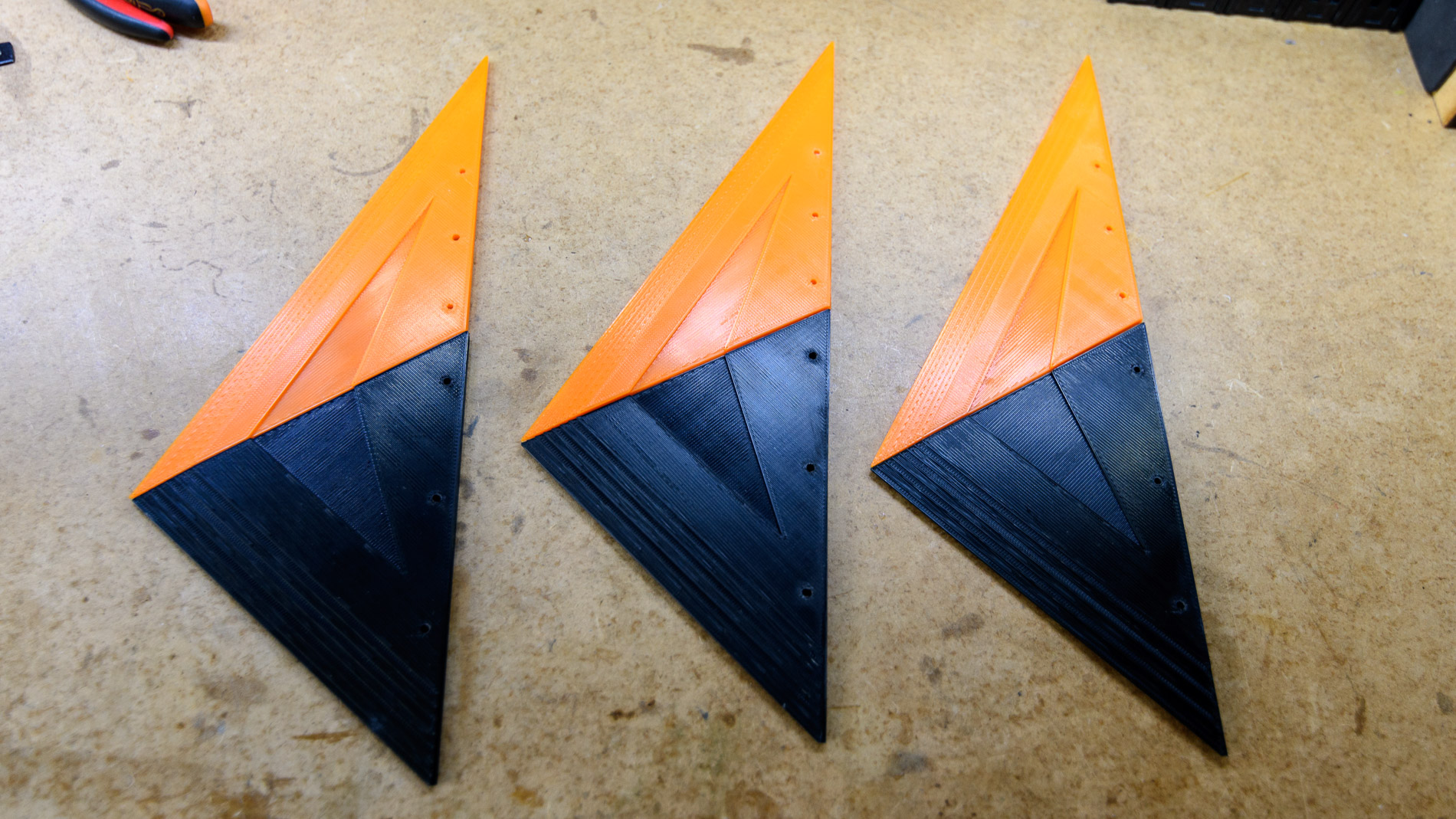
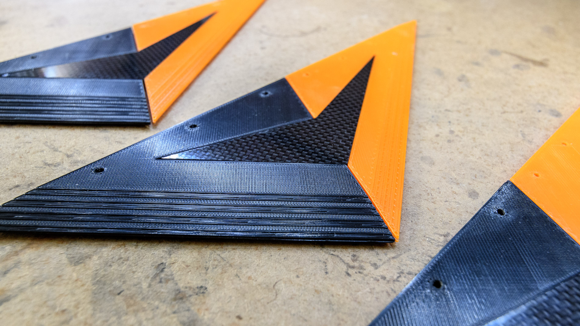
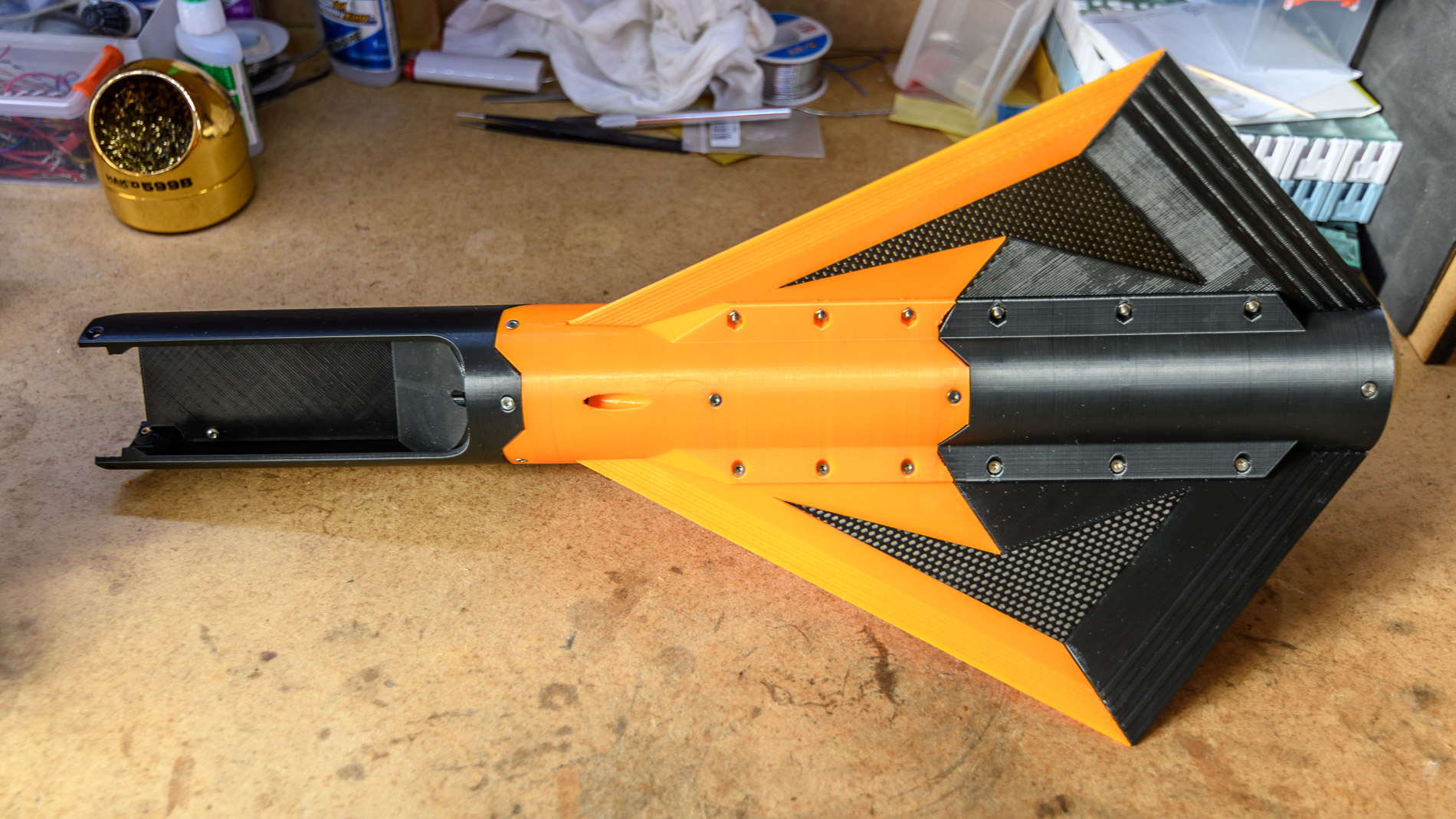
I opted for reducing to three ailerons, with an elongated triangular shape to increase the height of the center of aerodynamic pressure. 3 ailerons also meant I could launch from a launchpad of rail type (meaning the rockets has pads which slides in a rail under the ramp, instead of being guided inside the ramp like Cortex on the photo above). Rail ramps are good because they interfere less with telemetry and GPS signals. And it looks better on the photos.
The ailerons will also be bolted to the main fuselage, instead of being printed all in a single part. Cortex was actually entirely calculated around this : fitting the 4 ailerons on the Ultimakers2’s buildplate, and adjusting the other dimensions around that to design a stable rocket. But printing this 48 hours, 450g part proved to be a nightmare and failed three times in a raw due to miscellaneous issues with temperatures, filament and firmware bugs. Bolted ailerons it is. Actually, I think it looks even better.
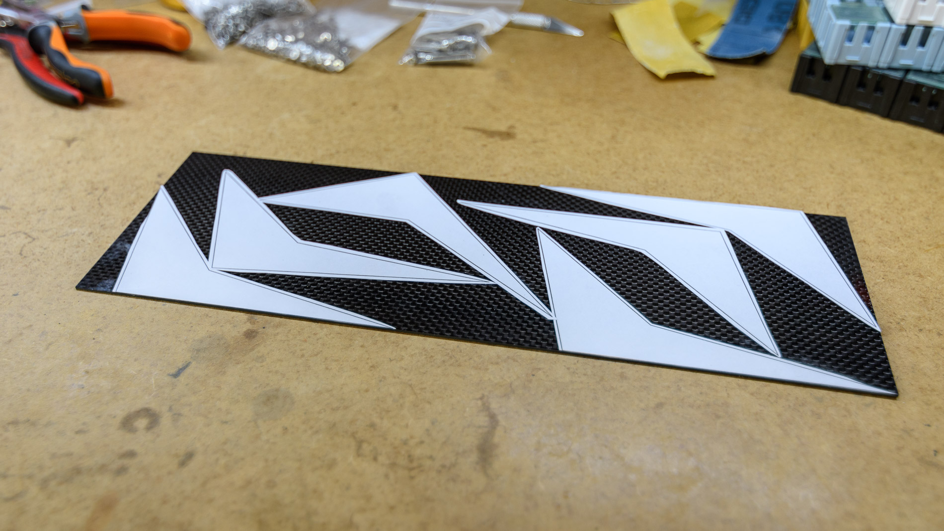
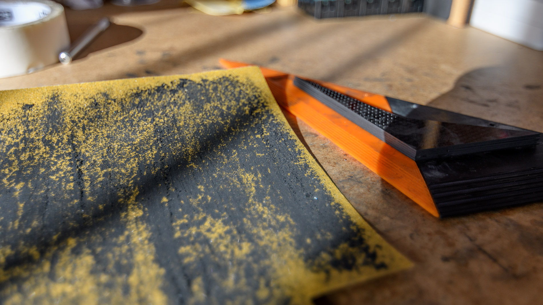
Cortex’s ailerons were also thick and heavy. I decided to make these ones thinner (down to 4mm from 7mm) by printing them in 4 parts and improving their rigidity with 1mm carbon fiber (which also reinforce the bonding between the upper and lower parts). Besides, carbon fiber always looks cool.


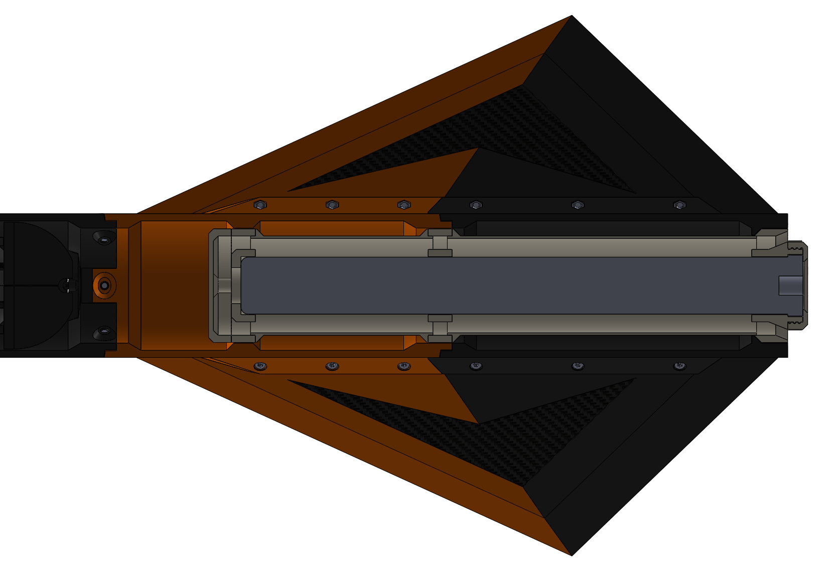
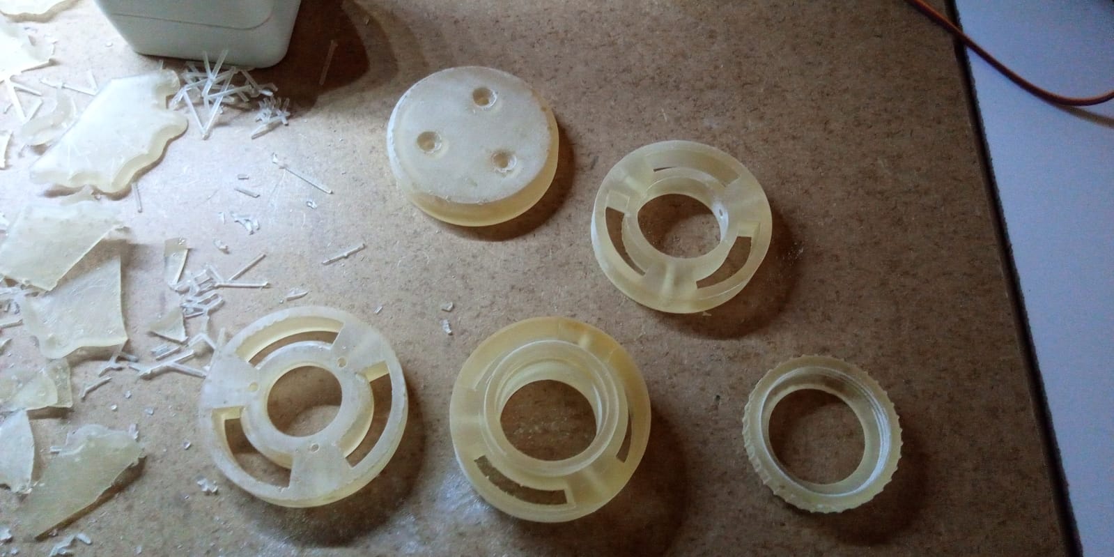
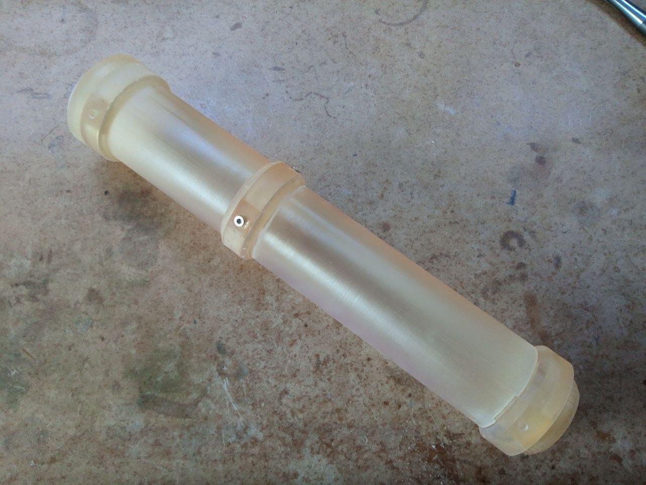
Motor casing
Another important aspect of the new motor is the delayed explosive charge at the upper end. This charge is supposed to generate a high-pressure burst of gas which ejects the parachute from the rocket when it has reached its apogee (the timer is configurable), and is useful for simple rockets without electronic timers. It is not allowed to use this system for this category of launches though, so the rocket must have a way to vent the gases outside (such as holes drilled in the fuselage next to the top of the motor). This is not good news, because high-pressure, high-temperature gases are the last thing you want inside a rocket 3D-printed in PLA that starts to melt at 60°C. The solution was a complete motor casing designed to guide the gases around the motor and vent them at the rear of the rocket (plus extra bonus thrust, yeah!). This casing was 3D-printed on an SLA printer with special high-temperature-resistant resin.

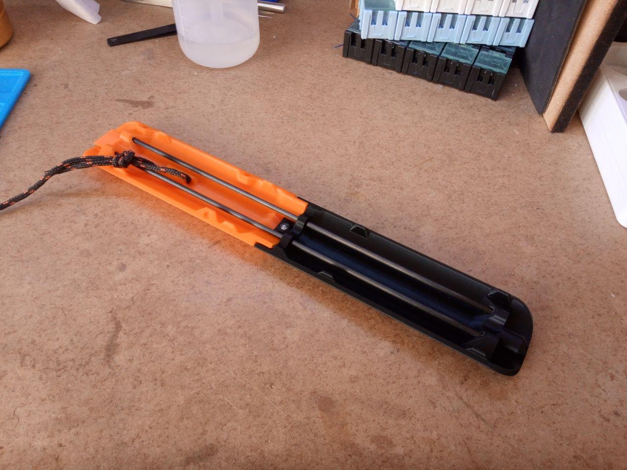
Parachute hatch
The main goal of engineering is to learn from one’s mistakes. It doesn’t matter if some wobbly bridge falls into a river as long as you learn something from it (at least if you are not under it at the wrong moment).
Cortex crashed because of two things :
- the parachute strap anchor on the hatch (which I forgot to include in the design) didn’t hold
- that hatch was too small and the parachute got stuck inside
The second problem came out of the fact that I wanted the hatch to fit into a single fuselage segment, for rigidity reasons. I feared that a cut on one side of a junction would bend the rocket and disqualify it (there is a “straightness” test during the qualification process). However, the strength of the structure of Cortex reassured me about the capabilities of the material, and I designed a 2-part hatch for Cortex 2. The hatch itself is reinforced with 3mm carbon fiber rods. Obviously, the parachute anchor is now strongly built-in. The hatch is released using a classic servo setup, and a set of reverse-mounted magnets push it away from the rocket.
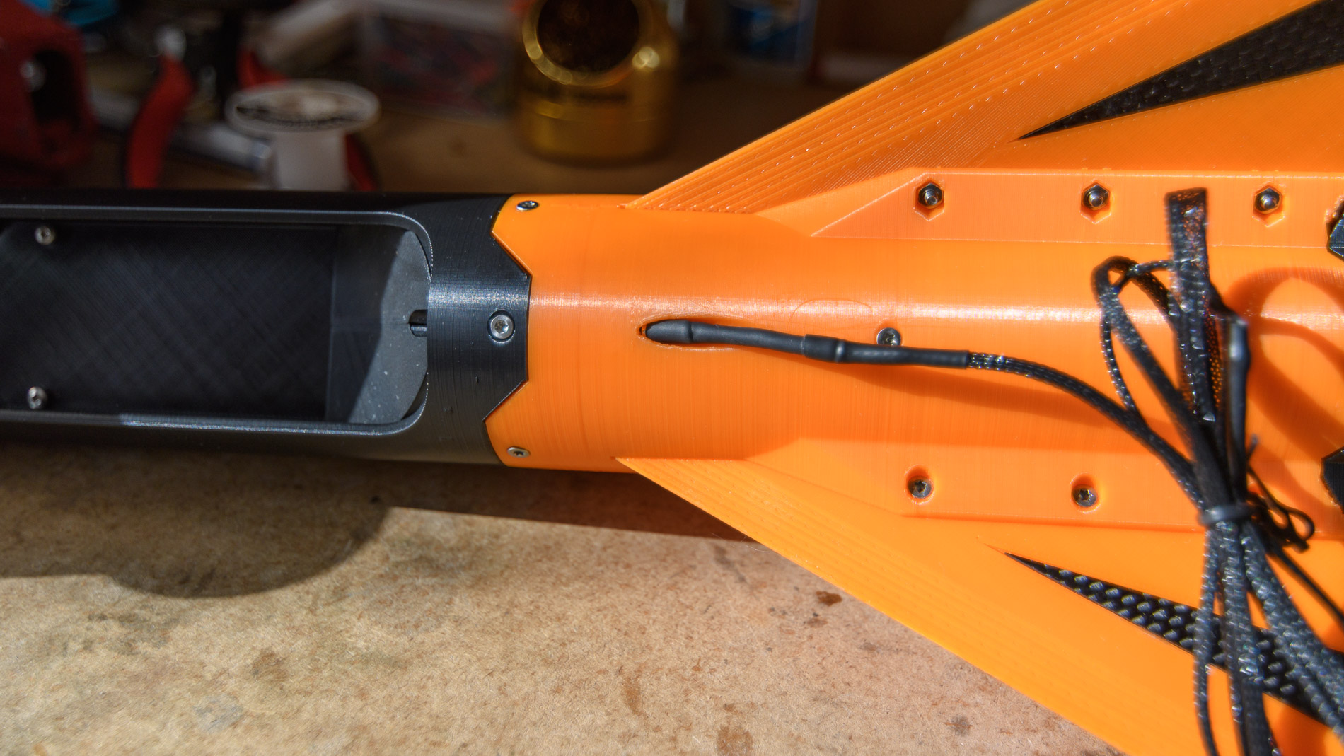
Jack
The rocket needs a way to know when the motor is fired in order to start the timer which will trigger the parachute ejection. While this can be done with an accelerometer, by far the most common and reliable way is plugging an audio jack on the side of the rocket and strapping it to the launchpad. Even a very simple RC analog timer can easily be triggered by a connector unplugging (therefore removing a short circuit), and microcontrollers only need a GPIO and a pull-up resistor.
Rocketry is already complicated enough as it is, better stick with the proven solutions.

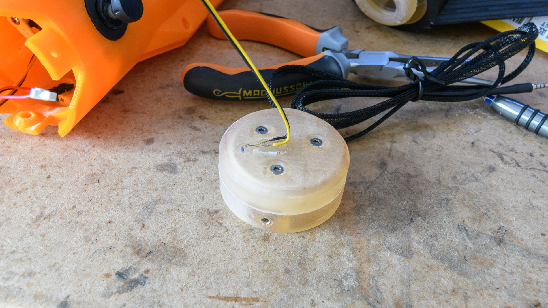
Temperature sensor
One of the experiences in Cortex was measuring the motor temperature during the flight. I found some spare temperature sensors and decided it would be easy enough to add one here. I thought it would be even more interesting to know the temperature of the gases that are expelled by the delayed charge, so I drilled a hole in the upper motor ring and secured the sensor into place with a drop of resin cured with a handheld UV lamp.
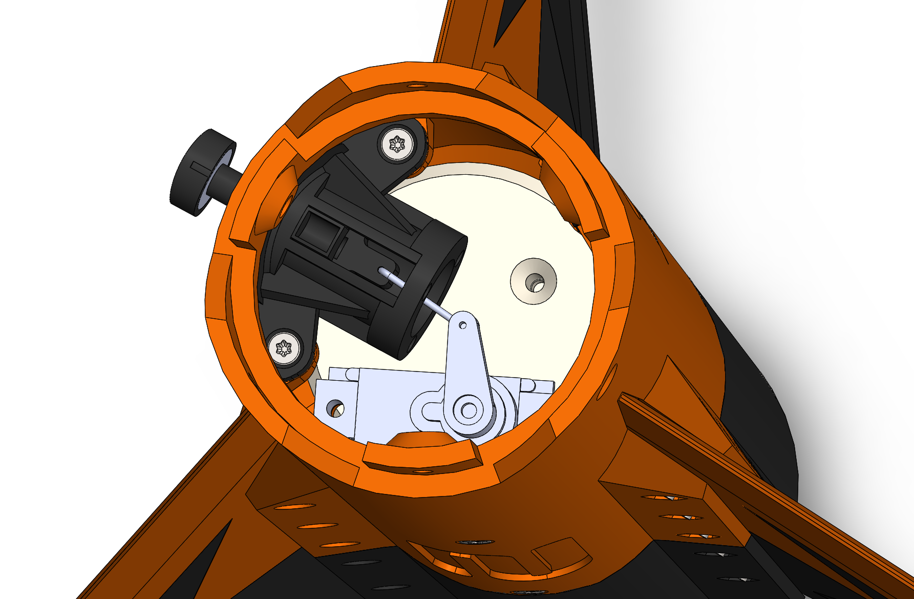
Pads
The pads are located on the side of the rocket and slide into the ramp to guide it on the launchpad. They are not good-looking and bad for the aerodynamic drag though. It would be great if they were retractable and could be pulled inside during the launch… How hard can it be?
What did I say about sticking to simple and reliable solutions again? Nevermind.
The mechanism is actually not that complicated. A microservo, a piano wire, and some more 3D-printed (SLA) parts. Small magnets ensure that the sliding part is in good contact with the stop of the fixed part, so that the servo never holds any weight. The surface in contact with the rail is a 10mm steel washer pushing on a 20mm screw firmly bolted inside the rocket. The assembly should be strong enough.

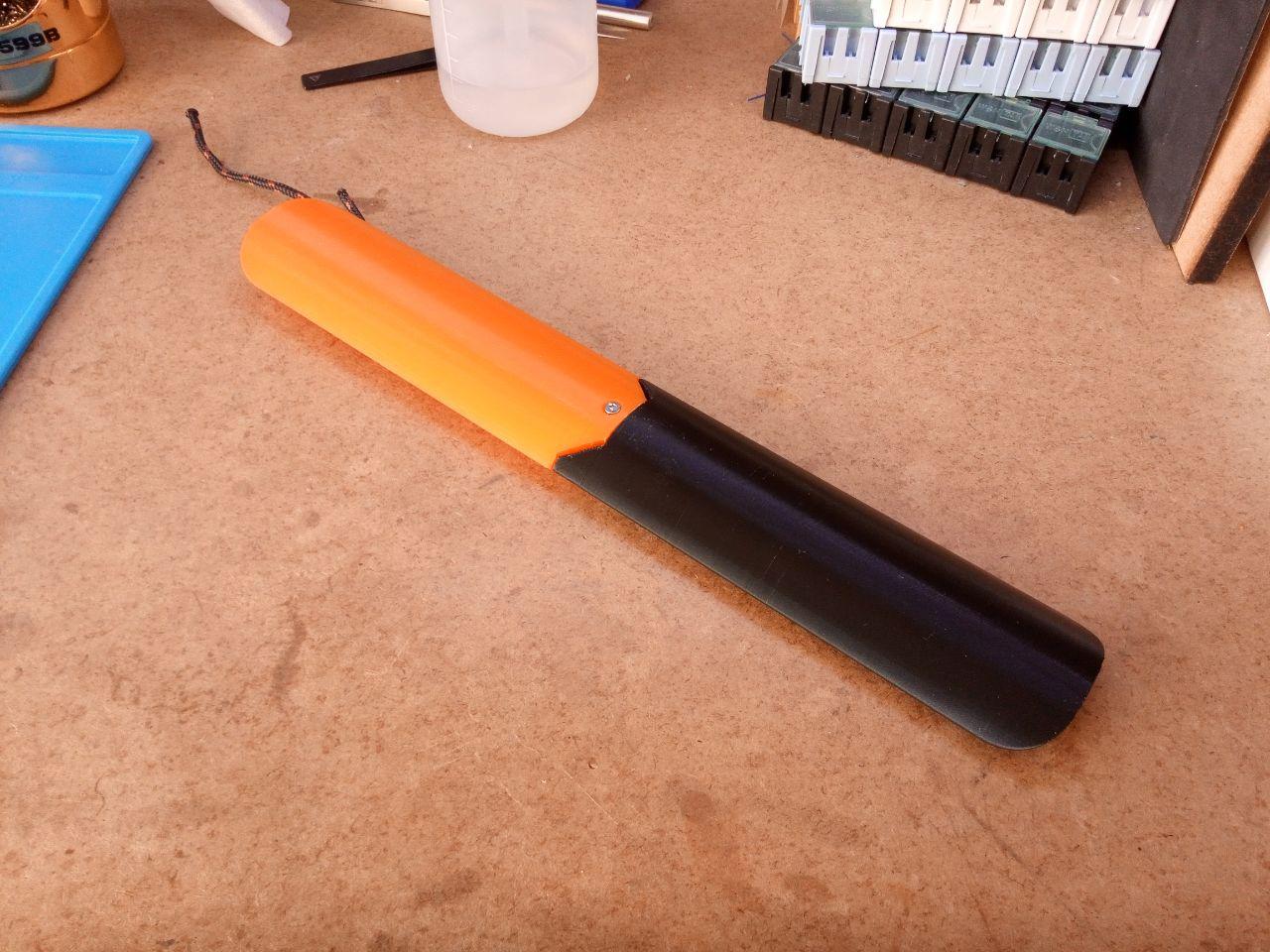
Parachute compartment
Only the bottom half is already printed. I’m waiting for the parachute to arrive from FruityChutes (a CFC-24) to measure its exact dimensions and place the separation on the upper half which will separate the parachute itself from its shroud lines (this is supposed to avoid the two to entangle together during the acceleration phase). Both halves have some room reserved on the rear to fit a battery and route the cables from the lower segment (temperature sensor, jack and servo) to the upper segment embedding the electronics. The battery can therefore be put in either segment, allowing a little bit of margin in the position of the center of mass.
That’s it for now. I’m waiting for some orders (parachute, electronic components) to be able to build the other half of the rocket. Stay tuned for another way-too-long build log!
The CTI pro 24 motors can have their ejection charge removed for rockets using electronic deployment. The last sentences of step one of the motor assembly manual addresses this. Also, in high power rocketry the most common method of detecting launch is a accelerometer detecting an acceleration over a threshold for a minimum time often coupled with a minimum altitude increase from a barometric sensor. No commercial hobby rocketry altimeter uses a disconnect, though that is a finger and likely reliable way to do it on a custom project like this.
Hi Brian,
Thanks for your comment, both your observations are indeed true. My choices can be explained by the context in which this rocket will be launched. I see from your website that you are located in the US, where (from what I understand) you can fire a rocket more or less freely as long as you pass the correct license. Here in France, the laws regarding motors are a lot more strict and the C’Space (organised by the french national space agency) is the only place where you can do this kind of project.
Regarding the ejection charge, students never touch the motors : only a handful of people in the organization team have the license to operate them. And since the launch schedule can be pretty tight, it’s usually not possible to ask them to remove the charge.
Regarding the jack, the main reasons are reliability and the qualification process. Relying on the accelerometer alone could trigger the system when the motor is installed or if something bumps into the rocket, and adding a condition on the barometer makes it impossible to realize a simulated flight (a general repetition of the flight on the ground when someone from the organization checks that the systems works as expected and the parachute deploys at the right time) which you must pass in order to qualify. Using an accelerometer and a barometer makes sense in an altimeter module which must be small and “all-included”, but when building a rocket from scratch (with the constraints I explained), a jack is way simpler and more reliable, and this is why it is used in 99% of the projects I see.
Plans on releasing the stl’s? 😀
If someone is interested, I will probably put that somewhere on github 🙂
Always interested in 3D Printed Rocketry 🙂
+1
Also interested!
did we ever gain access to these files anywhere?
Have you thought about using rollerons for self stabilization? On the Wikipedia rolleron article photo of the back end of an AIM-9 Sidewinder missile, there appear to be lengthwise pins inserted between the hinged flaps and the main fin. I assume the thrust of the rocket and the pins’ inertia causes them to fall out when the missile is launched. For a ground launched rocket those pins could be fixed to the launcher.
The launch rail and airflow should hold the flaps parallel to the fins until the gyro wheels get up to speed. From there the rollerons will move the same way the back of the rocket does in order to apply extra force to push it back. They’ll also self correct for spin/roll.
If the rocket doesn’t have enough time on the rail to spin up the rollers, use air jets during the launch sequence.
Great stuff. I had never heard about about rollerons before and I’ve never seen any project use them in the 5 years I’ve participated at this event. This is definitely something I would like to try if it is allowed by the range safety officer.
As you said, this category of rockets might not have enough speed and time in the air to see an effect, but it would be fun to verify. It could also be tested on the category above which uses Pro54 and Pro75 motors and offers much greater speeds.
Thanks for the tip!
Great work! Looking forward to electronics and chute packing.
Can you please send me the stl files?, I am interested in building the cortex 2.