Update : see the new version here.
Wired remote controls for DSLR cameras are incredibly cheap and are easy to find for about any camera brand out there nowadays. They prove very handy when you need to trigger the shot while you are away from the camera, such as for studio photography. The better ones even provide more advanced features such as delays and interval timers, features that are unfortunately not always provided by the cameras themselves.
When you need more range, for example for taking group photos or triggering two cameras distant from one another at the same time, wireless models on the 2.4GHz band offer a reliable solution for a few more bucks.
But what if you need more range?
Story time
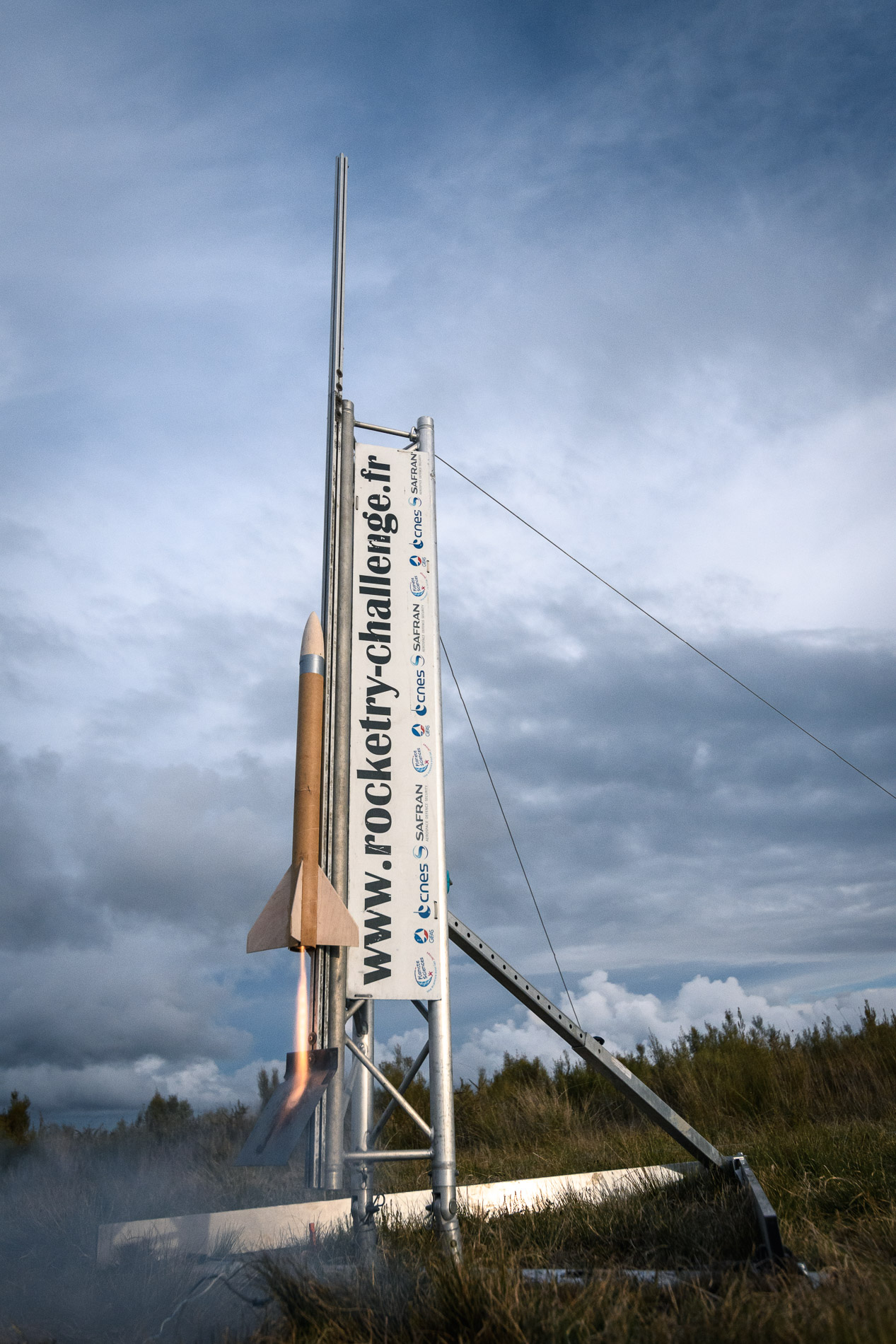
I faced this problem when I needed to take photos of experimental rockets launches. Obviously, you can’t (and don’t want to) be anywhere near the launchpad when the 9.1kg of high-power solid propellant of a Pro-98 motor are fired up. This called for a long-range remote that could trigger the camera(s) on the launchpad from a safer location about 600m away.

The current way of doing things is to use a proximity sensor on the ramp that detects when a fin passes in front of it and triggers the camera (see the photo above, about halfway up the ramp). This method works, but 1/ it requires more hardware that is not always available and 2/ it doesn’t allow to see the motor being lit up at the very beginning of the flight. A small, autonomous, long-range remote trigger would be much better.
Also, I needed a pretext to play with these LoRa modules that all the cool kids are using. That reason might have played its part in this project.
What do I need?
In the most basic form, a trigger button, a LoRa transmitter/receiver with its antenna, and a 2.5mm jack output. This is the standard used by some Canon cameras, by the current sensors system (this way it will be directly compatible), and most importantly, by almost all the cheap remote triggers out there which means adapter cables can be found for virtually any camera brand and connector.
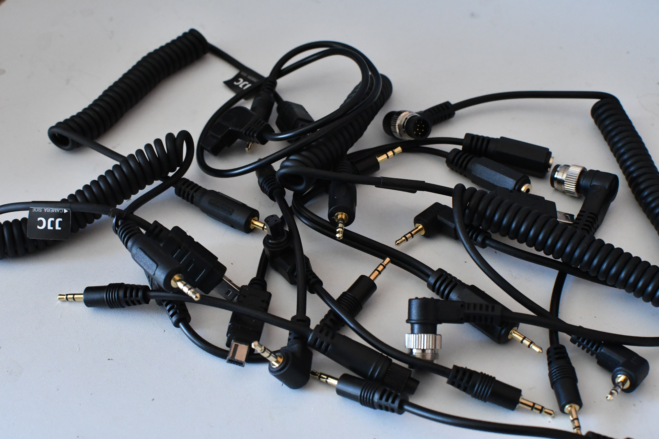
Another 2.5mm connector would be useful as an input. This way, the current system with the sensors can be used as a backup and trigger the camera even if the remote order is not received.
At this point, having one module dedicated for the remote control and one for the receiver didn’t seem very practical. A single design that can be used as either the transmitter or the receiver would be easier and way more versatile, you just need two of the same modules. Two or more actually, because any number of receivers can be used in order to control multiple cameras at the same time with a single remote (more on that below).
The modules needed to be autonomous, for obvious reasons. Let’s put a small LiPo battery with a LiPo charger IC and an USB connector on the list for the power supply side.
A microcontroller was needed to interface the LoRa module. An ATSAM4 with my libtungsten library was the obvious choice for this project.
Even cheap remotes feature interval timers, that can always be useful. And since I now had a reasonably powerful microcontroller, might as well use it. A few miniature pushbuttons and a small OLED screen would provide a nice user interface for this. The USB connector data lines could be connected as well, to allow a computer API to automate the system. This might seem a bit unnecessary, but I was planning for a very specific use case around this.
Let’s build it
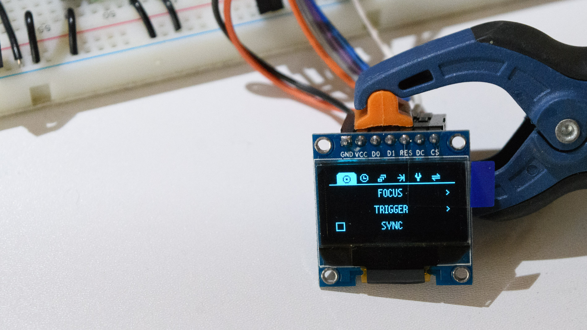
After I gathered the components, I quickly assembled a rough prototype on a breadboard in order to check that all the parts played nice with one another.

The microcontroller board is an old Carbide prototype. The LiPo is from Adafruit, the OLED display and LoRa modules are from AliExpress, and the breakout boards for the LoRa’s are from OSHPark. The Carbide’s LEDs are used to simulate the outputs, and the big pushbutton simulates the input.
Firmware and UI
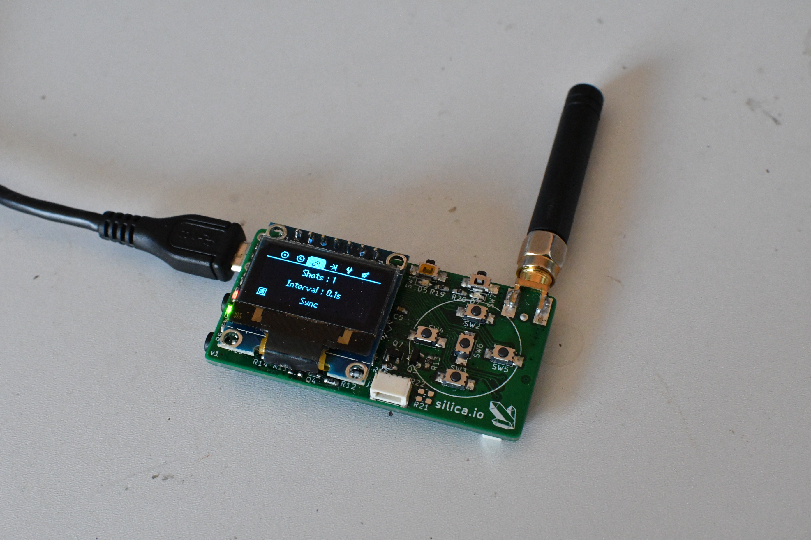
I started writing the firmware and implementing various features (spending way too much time drawing icons and fonts pixel-by-pixel in the process). The UI is built around 6 tabs : Trigger, Delay, Interval timer, Input, Settings, and Advanced (it changed a bit since the first version on the photo below). The Input can be set to Passthrough, Trigger, Trigger without delay, or Disabled.
Each tab can be independently synced by checking the box on the bottom. When a tab is synced, it means that :
– whenever a setting is changed by the user, the new setting is broadcast on the transmitter
– when a command or setting related to this tab is received on the receiver, it is executed / applied locally
This relatively simple scheme allows for a wide variety of scenarios. For example, imagine that you want to use two cameras to take images of a particular event from two points of views. You want one to trigger immediately when you press the button, and the other one to be delayed by a few tenths of a second. Each camera has a Silver module, and you have a third one in hand as the remote. All you need to do is check Sync on all three modules for the Trigger tab (so that the remote will broadcast the trigger order, and the receivers will listen for it), and check Sync on the Delay tab only for the remote and the second camera. For the first camera, Sync is disabled and the delay is set to 0s. This way, you will be able to control the delay remotely for the second camera, while it will stay to 0 on the first. Mixing Syncs and settings on different modules is a very versatile way to adapt to lots of complex scenarios where multiple points of views are needed.
For even more advanced use case, software channels are also implemented. The current channel can be selected in the Settings tab, and only the modules on the same channel will listen to this module’s commands.
All the code is available on Github.
A cleaner version
Once relatively functional and tested, the prototype was converted into a schematic on Kicad, and subsequently routed on a 4-layer board. Parts were carefully laid out such that it would allow a tight integration, with the screen board just above the largest part of the electronics (the plastic bit of the pinheader acting as a spacer) and the battery fitting on the bottom side between the jack connectors and the battery connector.
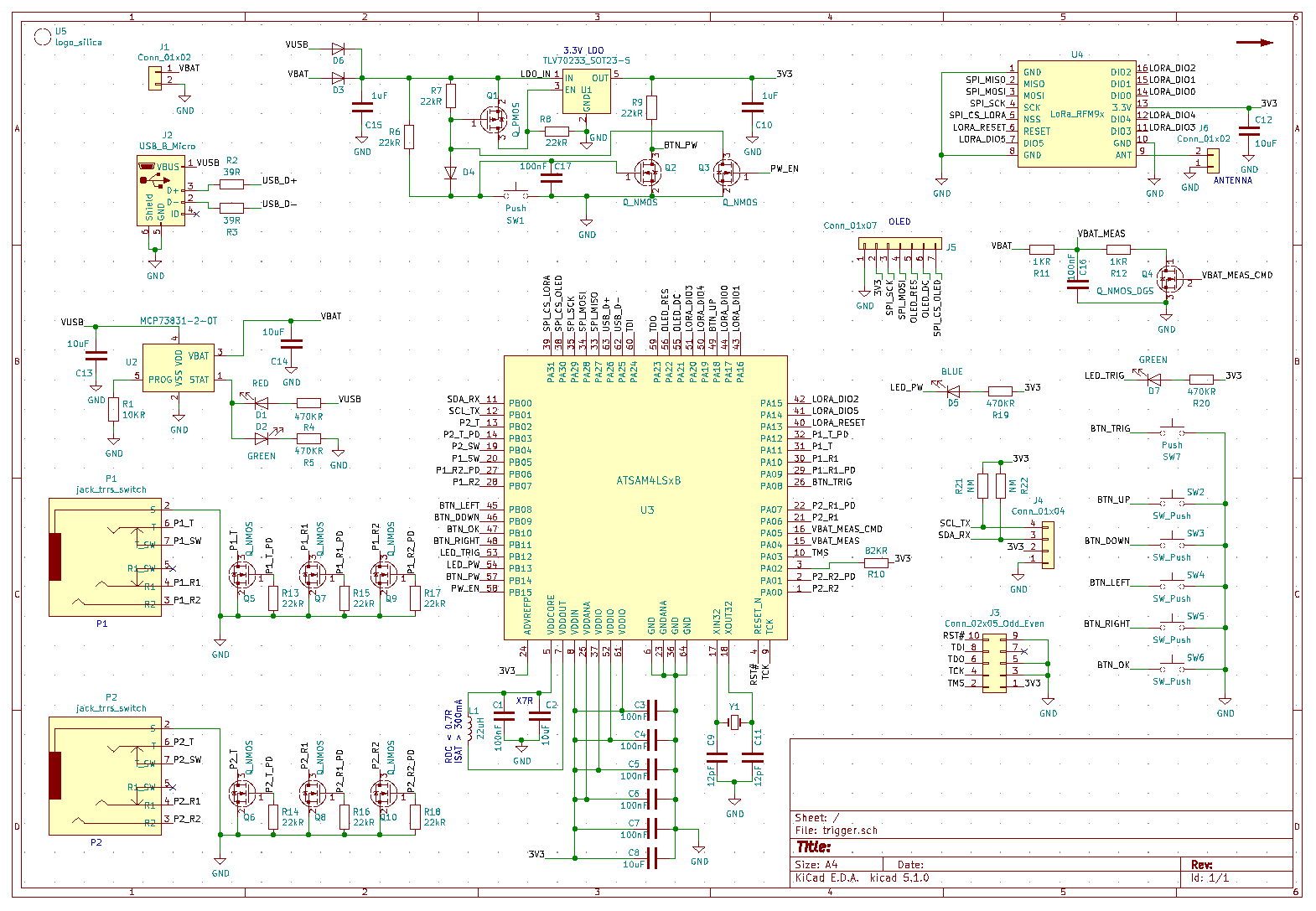
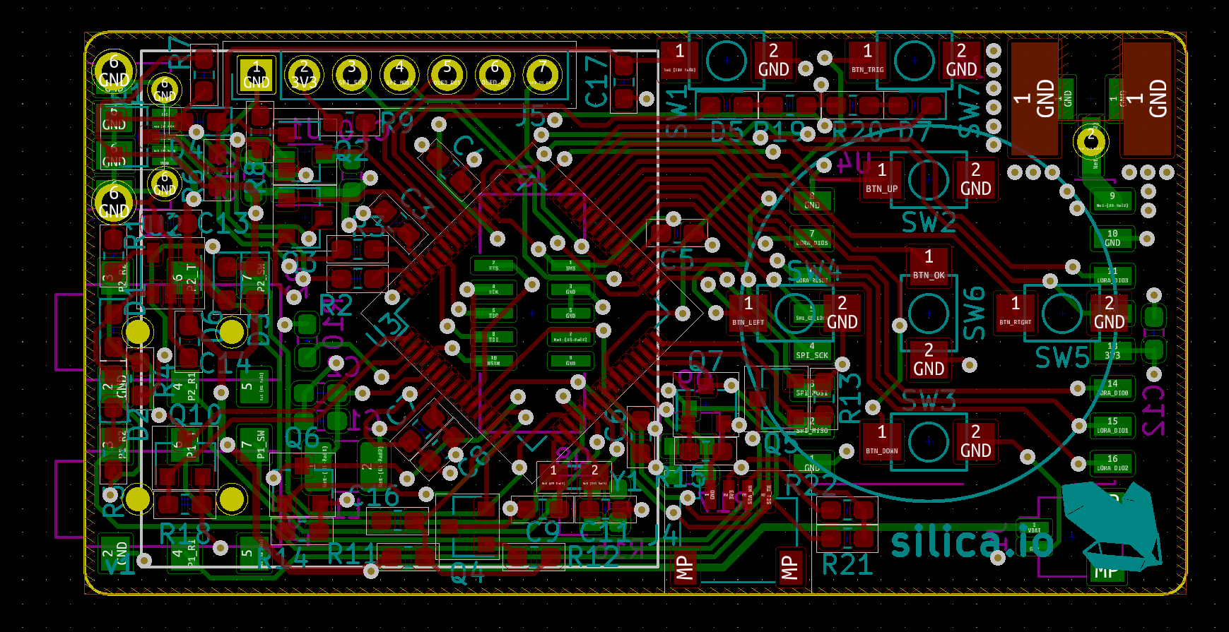

The Kicad project is available on Github.
The PCBs were ordered at JLCPCB, taking advantage of another order to minimize shipping cost (which tend to be pretty high using this service, even though the boards themselves are as cheap as they can be). The parts were mostly from Farnell (passives), Mouser (microcontroller, ICs) and AliExpress (buttons, screen, LoRa, SMA, antenna).
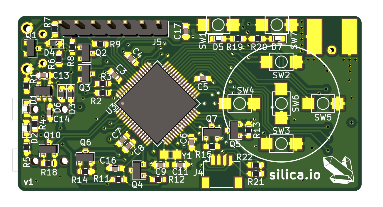
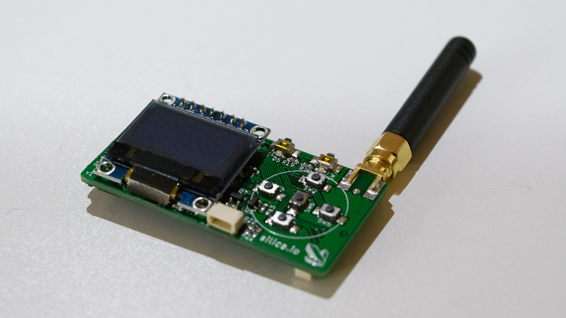
The result turned out as good as I could hope :
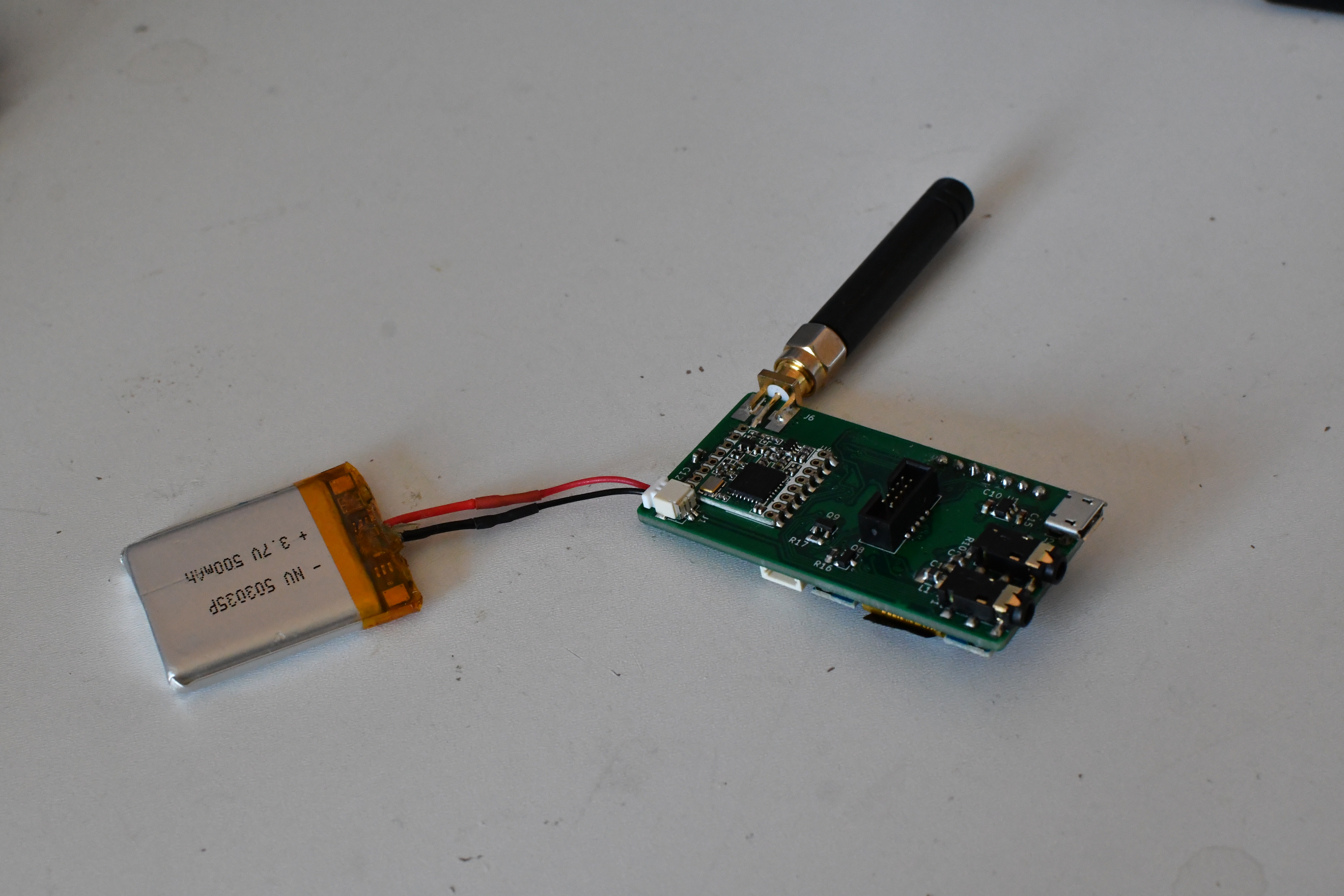
The large 10-pin connector on the middle of the bottom side is used for programming and debugging, and is only mounted on the two development prototypes. On the other prototypes, it is not mounted (a bootloader is written once into the microcontroller and the firmware is then uploaded via the USB connector), allowing the battery to fit just above the board.
Computer interface
Since the module has a USB connector, might as well use it and provide an computer user interface. This simple program was made using Qt and libusb, so it should be fairly easy to compile it on about any system. It mirrors the UI on the embedded display and every change on one is mirrored on the other. Obviously, if the current tab is synced it will also affect the other modules in range.

Using this, the camera can be easily controlled using any language supported by libusb. For example, only a few lines of Python are necessary. This will prove useful in rocket launches campaigns in order to have the launchpad management software automatically trigger the camera(s) at the end of the countdown.
Time for some testing
Four of these prototypes were tested in a rocket launch campaign recently and performed without a hitch, allowing to take the image below without the usual sensors on the launchpad. Great!
Range tests of more than 500m were also successful even when not in direct line of sight. I am currently planning for a more advanced test with logging of the distance and RSSI, and I’ve ordered a VSWR meter in order to test my antennas and make the whole system as reliable as possible.
The next step was making a case for this module. This was supposed to be a formality, but it proved way more interesting (and difficult) than expected and will therefore require a dedicated post. See you in the next episode!
I may start selling these modules in the future if enough people find them useful. Interested in buying one? Leave a comment below to let me know!
hi are these units for sale and if so where do I apply.
thanks
Tony
Hi, did you ever start selling these units?
This is awesome! I built a very very similar setup with an RF Arduino board years and years ago, but it was far more simple in functionality than yours. Madness be want to update mine…
Mine also was made very universal, but clunky, by using a cage built out of optical table components and a solenoid that physically presses the button on the camera. I’d definitely consider switching to yours if you’ve got some available or if I can find time to build them from your source.